Lexus RX (RX 350L, RX450h) 2016-2026 Repair Manual: Open in Outer Mirror Indicator(Master) (C1AB4)
DESCRIPTION
This DTC is stored when the blind spot monitor sensor LH detects an open in the outer rear view mirror indicator LH.
| DTC No. | Detection Item | DTC Detection Condition | Trouble Area |
|---|---|---|---|
| C1AB4 | Open in Outer Mirror Indicator(Master) | Both of the following conditions are met:
|
|
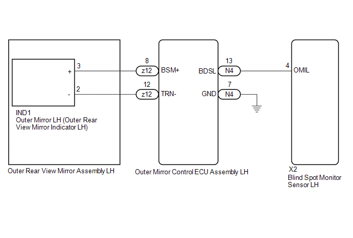
WIRING DIAGRAM
CAUTION / NOTICE / HINT
NOTICE:
When checking for DTCs, make sure that the blind spot monitor system is turned on.
PROCEDURE
| 1. | CHECK DTC |
(a) Turn the engine switch off.
(b) Turn the engine switch on (IG).
(c) Recheck for DTCs and check if the same DTC is output again.
Body Electrical > Blind Spot Monitor Master > Trouble CodesOK:
No DTCs are output.
| OK | .gif) | USE SIMULATION METHOD TO CHECK |
|
.gif)
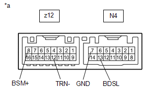
| 2. | CHECK HARNESS AND CONNECTOR (OUTER MIRROR CONTROL ECU ASSEMBLY LH - BLIND SPOT MONITOR SENSOR LH AND BODY GROUND) |
(a) Disconnect the X2 blind spot monitor sensor LH connector.
(b) Disconnect the N4 outer mirror control ECU assembly LH connector.
(c) Measure the resistance according to the value(s) in the table below.
Standard Resistance:
| Tester Connection | Condition | Specified Condition |
|---|---|---|
| X2-4 (OMIL) - N4-13 (BDSL) | Always | Below 1 Ω |
| N4-7 (GND) - Body ground | Always | Below 1 Ω |
| NG | | REPAIR OR REPLACE HARNESS OR CONNECTOR |
|
| 3. | INSPECT OUTER MIRROR CONTROL ECU ASSEMBLY LH |
(a) Disconnect the z12 outer rear view mirror assembly LH connector.
| (b) Measure the resistance according to the value(s) in the table below. Standard Resistance:
|
|
| NG | | REPLACE OUTER MIRROR CONTROL ECU ASSEMBLY LH |
|
| 4. | INSPECT OUTER REAR VIEW MIRROR ASSEMBLY LH |
(a) Disconnect the IND1 outer mirror LH connector.
(b) Measure the resistance according to the value(s) in the table below.
Standard Resistance:
| Tester Connection | Condition | Specified Condition |
|---|---|---|
| z12-8 (BSM+) - IND1-3 (+) | Always | Below 1 Ω |
| z12-12 (TRN-) - IND1-2 (-) | Always | Below 1 Ω |
| NG | | REPLACE OUTER REAR VIEW MIRROR ASSEMBLY LH |
|
| 5. | INSPECT OUTER MIRROR LH |
(a) Remove the outer mirror LH.
Click here .gif)
(b) Inspect the outer rear view mirror indicator LH on the outer mirror LH.
Click here
| OK | | REPLACE BLIND SPOT MONITOR SENSOR LH |
| NG | | REPLACE OUTER MIRROR LH |
 Short to GND in Outer Mirror Indicator(Slave) (C1AB3)
DESCRIPTION This DTC is stored when the blind spot monitor sensor RH detects a short to ground in the outer rear view mirror indicator RH. DTC No. Detection Item DTC Detection Condition Troub ...
 Open in Outer Mirror Indicator(Slave) (C1AB5)
DESCRIPTION This DTC is stored when the blind spot monitor sensor RH detects an open in the outer rear view mirror indicator RH. DTC No. Detection Item DTC Detection Condition Trouble Area ...
Other materials:
Lexus RX (RX 350L, RX450h) 2016-2026 Repair Manual > Audio And Visual System (for 8 Inch Display): Sound Quality is Bad Only when CD is Played (Volume is Too Low)
CAUTION / NOTICE / HINT NOTICE: Depending on the parts that are replaced during vehicle inspection or maintenance, performing initialization, registration or calibration may be needed. Refer to Precaution for Audio and Visual System. Click here PROCEDURE 1. REPLACE CD AND RECHECK (a) Repl ...
Lexus RX (RX 350L, RX450h) 2016-2026 Repair Manual > Airbag System: How To Proceed With Troubleshooting
CAUTION / NOTICE / HINT HINT:
Use the following procedure to troubleshoot the airbag system.
*: Use the Techstream.
PROCEDURE 1. VEHICLE BROUGHT TO WORKSHOP
NEXT 2. CUSTOMER PROBLEM ANALYSIS (a) Confirm problem symptoms. Click here
NEXT ...
Lexus RX (RX 350L, RX450h) 2016-{YEAR} Owners Manual
- For your information
- Pictorial index
- For safety and security
- Instrument cluster
- Operation of each component
- Driving
- Lexus Display Audio system
- Interior features
- Maintenance and care
- When trouble arises
- Vehicle specifications
- For owners
Lexus RX (RX 350L, RX450h) 2016-{YEAR} Repair Manual

0.0095