Lexus RX (RX 350L, RX450h) 2016-2026 Repair Manual: Removal
REMOVAL
CAUTION / NOTICE / HINT
The necessary procedures (adjustment, calibration, initialization, or registration) that must be performed after parts are removed and installed, or replaced during clearance warning ECU assembly removal/installation are shown below.
Necessary Procedures After Parts Removed/Installed/Replaced| Replaced Part or Performed Procedure | Necessary Procedure | Effect/Inoperative Function when Necessary Procedure not Performed | Link |
|---|---|---|---|
|
*1: When performing learning using the Techstream.
Click here | |||
| Disconnect cable from negative battery terminal | Memorize steering angle neutral point | Lane Control System | |
| Pre-collision System | |||
| Intelligent Clearance Sonar System*1 | |||
| Parking Assist Monitor System | | ||
| Panoramic View Monitor System | | ||
| Lighting System (w/ Automatic Headlight Beam Level Control System) | | ||
| Initialize back door lock | Power Door Lock Control System | | |
| Reset back door close position | Power Back Door System (w/ Outside Door Control Switch) | | |
| Replacement of clearance warning ECU assembly |
|
| |
PROCEDURE
1. PRECAUTION
NOTICE:
After turning the engine switch off, waiting time may be required before disconnecting the cable from the negative (-) battery terminal. Therefore, make sure to read the disconnecting the cable from the negative (-) battery terminal notices before proceeding with work.
Click here .gif)
2. DISCONNECT CABLE FROM NEGATIVE BATTERY TERMINAL
NOTICE:
When disconnecting the cable, some systems need to be initialized after the cable is reconnected.
Click here
3. REMOVE LOWER NO. 1 INSTRUMENT PANEL FINISH PANEL
Click here
4. REMOVE INSTRUMENT PANEL GARNISH RH
Click here
5. REMOVE FRONT DOOR SCUFF PLATE RH
HINT:
Use the same procedure as for the LH side.
Click here
6. REMOVE COWL SIDE TRIM BOARD RH
HINT:
Use the same procedure as for the LH side.
Click here
7. REMOVE NO. 2 INSTRUMENT PANEL UNDER COVER SUB-ASSEMBLY
Click here
8. REMOVE GLOVE COMPARTMENT DOOR ASSEMBLY
Click here
9. REMOVE PARKING ASSIST ECU (w/ Panoramic View Monitor System)
Click here
10. REMOVE ECU INTEGRATION BOX RH
| (a) Disconnect each connector. |
|
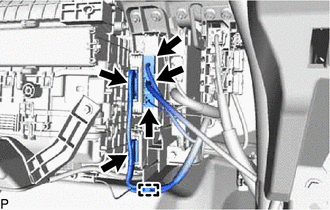
(b) Disengage the clamp.
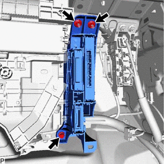
| (c) Remove the bolt, 2 nuts and ECU integration box RH. |
|
11. REMOVE CLEARANCE WARNING ECU ASSEMBLY
(a) Disengage the 2 claws and remove the clearance warning ECU assembly as shown in the illustration.
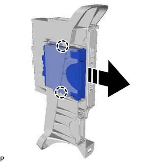
.png) | Remove in this Direction |
 Installation
INSTALLATION PROCEDURE 1. INSTALL CLEARANCE WARNING ECU ASSEMBLY (a) Engage the 2 claws to install the clearance warning ECU assembly as shown in the illustration. Install in this Direction ...

Other materials:
Lexus RX (RX 350L, RX450h) 2016-2026 Repair Manual > Audio And Visual System (for 12.3 Inch Display): Portable Player cannot be Registered
CAUTION / NOTICE / HINT HINT: Some versions of "Bluetooth" compatible audio players may not function properly, or the functions may be limited using the radio receiver assembly, even if the portable audio player itself can play files. Click here PROCEDURE 1. CHECK THAT PORTABLE PLAYER IS "Bl ...
Lexus RX (RX 350L, RX450h) 2016-2026 Repair Manual > Charging System: Freeze Frame Data
FREEZE FRAME DATA DESCRIPTION The ECM records vehicle and driving condition information as freeze frame data the moment a DTC is stored. When troubleshooting, freeze frame data can be helpful in determining whether the vehicle was moving or stationary, whether the engine was warmed up or not, whethe ...
Lexus RX (RX 350L, RX450h) 2016-{YEAR} Owners Manual
- For your information
- Pictorial index
- For safety and security
- Instrument cluster
- Operation of each component
- Driving
- Lexus Display Audio system
- Interior features
- Maintenance and care
- When trouble arises
- Vehicle specifications
- For owners
Lexus RX (RX 350L, RX450h) 2016-{YEAR} Repair Manual

0.012