Lexus RX (RX 350L, RX450h) 2016-2026 Repair Manual: No. 1 Clearance Warning Buzzer Circuit
DESCRIPTION
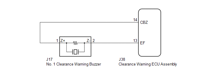
This circuit consists of the No. 1 clearance warning buzzer and clearance warning ECU assembly. An ECU-excited type buzzer is used. The ECU operates the buzzers using a sound pattern that changes depending on the distance to the obstacle.
WIRING DIAGRAM
PROCEDURE
| 1. | PERFORM ACTIVE TEST USING TECHSTREAM |
(a) Connect the Techstream to the DLC3.
(b) Turn the engine switch on (IG).
(c) Turn the Techstream on.
(d) Enter the following menus: Body Electrical / Advanced Parking Guidance/ICS/Intuitive P/A / Active Test.
(e) Check that the buzzer operates by performing the Active Test.
Body Electrical > Advanced Parking Guidance/ICS/Intuitive P/A > Active Test| Tester Display | Measurement Item | Control Range | Diagnostic Note |
|---|---|---|---|
| Front Buzzer | No. 1 clearance warning buzzer | Stop or Operate | Confirm that the vehicle is stopped and the engine switch is on (IG) |
| Tester Display |
|---|
| Front Buzzer |
OK:
The No. 1 clearance warning buzzer sounds.
| OK |  | REPLACE CLEARANCE WARNING ECU ASSEMBLY |
|

| 2. | CHECK HARNESS AND CONNECTOR (CLEARANCE WARNING ECU ASSEMBLY - NO. 1 CLEARANCE WARNING BUZZER) |
(a) Disconnect the J38 clearance warning ECU assembly connector.
(b) Disconnect the J17 No. 1 clearance warning buzzer connector.
(c) Measure the resistance according to the value(s) in the table below.
Standard Resistance:
| Tester Connection | Condition | Specified Condition |
|---|---|---|
| J38-14 (CBZ) - J17-1 (Z+) | Always | Below 1 Ω |
| J38-13 (EF) - J17-2 (Z-) | Always | Below 1 Ω |
| J38-14 (CBZ) or J17-1 (Z+) - Body ground | Always | 10 kΩ or higher |
| J38-13 (EF) or J17-2 (Z-) - Body ground | Always | 10 kΩ or higher |
| NG | | REPAIR OR REPLACE HARNESS OR CONNECTOR |
|
| 3. | REPLACE NO. 1 CLEARANCE WARNING BUZZER |
(a) Replace the No. 1 clearance warning buzzer with a new or known good one.
Click here .gif)
|
| 4. | PERFORM ACTIVE TEST USING TECHSTREAM |
(a) Connect the Techstream to the DLC3.
(b) Turn the engine switch on (IG).
(c) Turn the Techstream on.
(d) Enter the following menus: Body Electrical / Advanced Parking Guidance/ICS/Intuitive P/A / Active Test.
(e) Check that the buzzer operates by performing the Active Test.
Body Electrical > Advanced Parking Guidance/ICS/Intuitive P/A > Active Test| Tester Display | Measurement Item | Control Range | Diagnostic Note |
|---|---|---|---|
| Front Buzzer | No. 1 clearance warning buzzer | Stop or Operate | Confirm that the vehicle is stopped and the engine switch is on (IG) |
| Tester Display |
|---|
| Front Buzzer |
OK:
The No. 1 clearance warning buzzer sounds.
| OK | | END |
| NG | | REPLACE CLEARANCE WARNING ECU ASSEMBLY |
 CAN Communication Failure (Message Registry) (U1000)
DESCRIPTION If DTC U1000 is stored frequently, duplicate the conditions that cause the problem symptoms and perform the inspection again even if the DTC is not output when rechecking for DTCs. DTC ...
 Clearance Warning ECU Power Source Circuit
DESCRIPTION This circuit provides power to operate the clearance warning ECU assembly. WIRING DIAGRAM CAUTION / NOTICE / HINT NOTICE: Inspect the fuses for circuits related to this system before perf ...
Other materials:
Lexus RX (RX 350L, RX450h) 2016-2026 Repair Manual > Lin Communication System: Data List / Active Test
DATA LIST / ACTIVE TEST DATA LIST HINT: Using the Techstream to read the Data List allows the values or states of switches, sensors, actuators and other items to be read without removing any parts. This non-intrusive inspection can be very useful because intermittent conditions or signals may be dis ...
Lexus RX (RX 350L, RX450h) 2016-2026 Repair Manual > Audio And Visual System (for 8 Inch Display): Steering Pad Switch Circuit
DESCRIPTION This circuit sends an operation signal from the steering pad switch assembly to the radio receiver assembly. If there is an open in the circuit, the audio system cannot be operated using the steering pad switch assembly. If there is a short in the circuit, the same condition as when a sw ...
Lexus RX (RX 350L, RX450h) 2016-{YEAR} Owners Manual
- For your information
- Pictorial index
- For safety and security
- Instrument cluster
- Operation of each component
- Driving
- Lexus Display Audio system
- Interior features
- Maintenance and care
- When trouble arises
- Vehicle specifications
- For owners
Lexus RX (RX 350L, RX450h) 2016-{YEAR} Repair Manual

0.0101