Lexus RX (RX 350L, RX450h) 2016-2026 Repair Manual: System Description
SYSTEM DESCRIPTION
OPERATION EXPLANATION
(a) The reverse position signal is sent from the shift lever position switch to the parking assist ECU when the shift lever is moved to R.
(b) An appropriate steering angle and timing information can be provided for the driver. This is based on the information from the steering angle sensor signal and the vehicle angle data signal that are sent to the parking assist ECU.
HINT:
The steering angle sensor signal is used to control parking assist only for estimated guide line mode.
COMMUNICATION SYSTEM OUTLINE
(a) CAN communication system
(1) The panoramic view monitor system uses CAN communication for data communications between the parking assist ECU and each ECU.
(2) If a problem occurs in the CAN communication line, the parking assist ECU outputs a CAN communication malfunction DTC. (To check, use the Techstream.)
Click here .gif)
(3) If a problem occurs in the CAN communication line, the parking assist ECU outputs a CAN communication malfunction DTC. (To check, use the radio receiver assembly diagnosis screen.)
Click here
(4) If a CAN communication line malfunction DTC is output, repair the malfunction in the communication line and troubleshoot the panoramic view monitor system when data communication is normal.
(5) Since the CAN communication line has its own length and route, it cannot be repaired temporarily with a bypass wire, etc.
VIDEO SIGNALS
(a) Video signal circuit
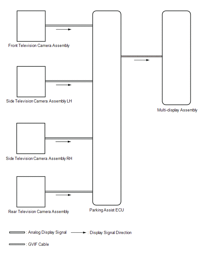
(1) Video signals from the front television camera assembly are input into the parking assist ECU via analog communication lines (vehicle wire harness).
(2) Video signals from the side television camera assembly LH are input into the parking assist ECU via analog communication lines (vehicle wire harness).
(3) Video signals from the side television camera assembly RH are input into the parking assist ECU via analog communication lines (vehicle wire harness).
(4) Video signals from the rear television camera assembly are input into the parking assist ECU via analog communication lines (vehicle wire harness).
(5) Video signals from the parking assist ECU are input into the multi-display assembly via GVIF cable.
(b) Screen display
(1) Video signals input from each camera are processed in the parking assist ECU and displayed on the multi-display assembly as the panoramic view monitor system screen.
DIAGNOSTIC FUNCTION OUTLINE
(a) This panoramic view monitor system has a diagnostic function displayed in the multi-display assembly. This function enables the calibration (adjustment and verification) of the panoramic view monitor system.
Click here
(b) The panoramic view monitor system can check the following items by using the Techstream.
| Item | Proceed to |
|---|---|
| DTC | |
| Data List / Active Test | |
CALIBRATION
(a) Use the panoramic view monitor system diagnosis screen for calibration and checking of the panoramic view monitor system.
Click here
NOTICE:
Part replacement and work performed during servicing may require calibration of the panoramic view monitor system and other systems.
Click here
 System Diagram
SYSTEM DIAGRAM ...
 How To Proceed With Troubleshooting
CAUTION / NOTICE / HINT HINT:
Use the following procedure to troubleshoot the panoramic view monitor system.
*: Use the Techstream.
PROCEDURE 1. VEHICLE BROUGHT TO WORKSHOP
NEXT ...
Other materials:
Lexus RX (RX 350L, RX450h) 2016-2026 Repair Manual > Airbag System: Seat Belt Buckle Switch (LH) (B1656)
DESCRIPTION The front seat belt buckle switch LH circuit consists of the airbag sensor assembly and front seat belt buckle switch LH (front seat inner belt assembly LH). DTC B1656 is stored when a malfunction is detected in the front seat belt buckle switch LH circuit. DTC No. Detection Item ...
Lexus RX (RX 350L, RX450h) 2016-2026 Repair Manual > Brake Pedal: Components
COMPONENTS ILLUSTRATION *1 BRAKE PEDAL RETURN SPRING *2 BRAKE PEDAL SUPPORT ASSEMBLY *3 PUSH ROD PIN *4 STOP LIGHT SWITCH ASSEMBLY *5 BRAKE MASTER CYLINDER PUSH ROD CLEVIS *6 LOCK NUT *7 WIRE HARNESS - - Tightening torque for "Major areas involving basi ...
Lexus RX (RX 350L, RX450h) 2016-{YEAR} Owners Manual
- For your information
- Pictorial index
- For safety and security
- Instrument cluster
- Operation of each component
- Driving
- Lexus Display Audio system
- Interior features
- Maintenance and care
- When trouble arises
- Vehicle specifications
- For owners
Lexus RX (RX 350L, RX450h) 2016-{YEAR} Repair Manual

0.0089