Lexus RX (RX 350L, RX450h) 2016-2026 Repair Manual: Side Camera Current Malfunction (C1684)
DESCRIPTION
This DTC is stored if the parking assist ECU judges as a result of its self check that a synchronization problem is occurring in the image signal sent from the passenger side television camera assembly to the parking assist ECU.
| DTC No. | Detection Item | DTC Detection Condition | Trouble Area |
|---|---|---|---|
| C1684 | Side Camera Current Malfunction | Side camera current malfunction |
|
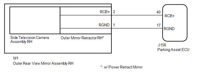
- *: w/ Power Retract Mirror
WIRING DIAGRAM
CAUTION / NOTICE / HINT
NOTICE:
-
When "!" is displayed on the multi-display assembly after the cable is disconnected from the negative (-) battery terminal, correct the steering angle neutral point.
Click here
.gif)
-
Depending on the parts that are replaced or operations that are performed during vehicle inspection or maintenance, calibration of other systems as well as the panoramic view monitor system may be needed.
Click here
PROCEDURE
| 1. | CHECK FOR DTC |
(a) Clear the DTCs.
Chassis > Circumference Monitoring Camera Control Module > Clear DTCs(b) Check for DTCs.
Chassis > Circumference Monitoring Camera Control Module > Trouble CodesOK:
DTC C1684 is not output.
| OK | .gif) | USE SIMULATION METHOD TO CHECK |
|
.gif)
| 2. | CHECK HARNESS AND CONNECTOR (PARKING ASSIST ECU - OUTER REAR VIEW MIRROR ASSEMBLY RH) |
(a) Disconnect the J158 parking assist ECU connector.
(b) Disconnect the M1 outer rear view mirror assembly RH connector.
(c) Measure the resistance according to the value(s) in the table below.
Standard Resistance:
| Tester Connection | Condition | Specified Condition |
|---|---|---|
| J158-40 (RCB+) - M1-2 (RCB+) | Always | Below 1 Ω |
| J158-17 (RGND) - M1-1 (RGND) | Always | Below 1 Ω |
| J158-40 (RCB+) or M1-2 (RCB+) - Body ground | Always | 10 kΩ or higher |
| J158-17 (RGND) or M1-1 (RGND) - Body ground | Always | 10 kΩ or higher |
| NG | | REPAIR OR REPLACE HARNESS OR CONNECTOR |
|
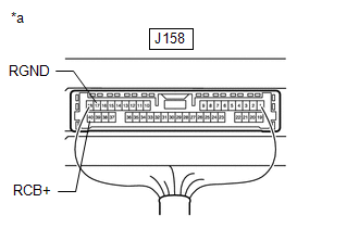
| 3. | CHECK PARKING ASSIST ECU (RCB+, RGND) |
| (a) Connect the J158 parking assist ECU connector. |
|
(b) Measure the resistance according to the value(s) in the table below.
Standard Resistance:
| Tester Connection | Condition | Specified Condition |
|---|---|---|
| J158-17 (RGND) - Body ground | Always | Below 1 Ω |
(c) Measure the voltage according to the value(s) in the table below.
Standard Voltage:
| Tester Connection | Switch Condition | Specified Condition |
|---|---|---|
| J158-40 (RCB+) - J158-17 (RGND) | Engine switch on (IG) | 5.5 to 7.05 V |
| NG | | REPLACE PARKING ASSIST ECU |
|
| 4. | REPLACE SIDE TELEVISION CAMERA ASSEMBLY RH |
(a) Replace the side television camera assembly RH with a new or normally functioning one.
Click here
|
| 5. | CHECK FOR DTC |
(a) Clear the DTCs.
Chassis > Circumference Monitoring Camera Control Module > Clear DTCs(b) Check for DTCs.
Chassis > Circumference Monitoring Camera Control Module > Trouble CodesOK:
DTCs C1684 is not output.
| Result | Proceed to |
|---|---|
| OK | A |
| NG (w/ Power Retract Mirror) | B |
| NG (w/o Power Retract Mirror) | C |
| A | | END (SIDE TELEVISION CAMERA ASSEMBLY RH WAS DEFECTIVE) |
| B | | REPLACE OUTER MIRROR RETRACTOR RH |
| C | | REPLACE OUTER REAR VIEW MIRROR ASSEMBLY RH |
 Side Camera Feedback Malfunction (C1683)
DESCRIPTION This DTC is stored if the parking assist ECU judges as a result of its self check that a synchronization problem is occurring in the image signal sent from the passenger side television ca ...
 Driver Side Camera Video Sync Signal Malfunction (C1686)
DESCRIPTION This DTC is stored if the parking assist ECU judges as a result of its self check that a synchronization problem is occurring in the image signal sent from the driver side television camer ...
Other materials:
Lexus RX (RX 350L, RX450h) 2016-2026 Repair Manual > Transfer System: Precaution
PRECAUTION PRECAUTION (a) Prior to starting any work, clean the transfer assembly to prevent sand or mud deposits from entering the assembly. (b) When removing any light alloy components such as the transfer cover, do not pry on the component with a screwdriver or similar tool. Tap the component loo ...
Lexus RX (RX 350L, RX450h) 2016-2026 Repair Manual > Seat Belt Warning System: Parts Location
PARTS LOCATION ILLUSTRATION *1 AIRBAG SENSOR ASSEMBLY *2 ECM *3 SKID CONTROL ECU (BRAKE ACTUATOR ASSEMBLY) *4 DLC3 *5 MAIN BODY ECU (MULTIPLEX NETWORK BODY ECU) *6 INSTRUMENT PANEL JUNCTION BLOCK ASSEMBLY *7 ENGINE ROOM RELAY BLOCK AND JUNCTION BLOCK ASSEMBLY - EC ...
Lexus RX (RX 350L, RX450h) 2016-{YEAR} Owners Manual
- For your information
- Pictorial index
- For safety and security
- Instrument cluster
- Operation of each component
- Driving
- Lexus Display Audio system
- Interior features
- Maintenance and care
- When trouble arises
- Vehicle specifications
- For owners
Lexus RX (RX 350L, RX450h) 2016-{YEAR} Repair Manual

0.0106