Lexus RX (RX 350L, RX450h) 2016-2026 Repair Manual: Driver Side Camera Video Sync Signal Malfunction (C1686)
DESCRIPTION
This DTC is stored if the parking assist ECU judges as a result of its self check that a synchronization problem is occurring in the image signal sent from the driver side television camera assembly to the parking assist ECU.
| DTC No. | Detection Item | DTC Detection Condition | Trouble Area |
|---|---|---|---|
| C1686 | Driver Side Camera Video Sync Signal Malfunction | Side camera feedback malfunction |
|
- *: w/ Power Retract Mirror
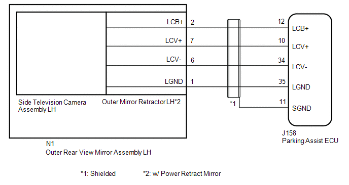
WIRING DIAGRAM
CAUTION / NOTICE / HINT
NOTICE:
-
When "!" is displayed on the multi-display assembly after the cable is disconnected from the negative (-) battery terminal, correct the steering angle neutral point.
Click here
.gif)
-
Depending on the parts that are replaced or operations that are performed during vehicle inspection or maintenance, calibration of other systems as well as the panoramic view monitor system may be needed.
Click here
PROCEDURE
| 1. | CHECK FOR DTC |
(a) Clear the DTCs.
Chassis > Circumference Monitoring Camera Control Module > Clear DTCs(b) Check for DTCs.
Chassis > Circumference Monitoring Camera Control Module > Trouble CodesOK:
DTC C1686 is not output.
| OK |  | USE SIMULATION METHOD TO CHECK |
|

| 2. | CHECK HARNESS AND CONNECTOR (PARKING ASSIST ECU - OUTER REAR VIEW MIRROR ASSEMBLY LH) |
(a) Disconnect the J158 parking assist ECU connector.
(b) Disconnect the N1 outer rear view mirror assembly LH connector.
(c) Measure the resistance according to the value(s) in the table below.
Standard Resistance:
| Tester Connection | Condition | Specified Condition |
|---|---|---|
| J158-12 (LCB+) - N1-2 (LCB+) | Always | Below 1 Ω |
| J158-10 (LCV+) - N1-7 (LCV+) | Always | Below 1 Ω |
| J158-34 (LCV-) - N1-6 (LCV-) | Always | Below 1 Ω |
| J158-35 (LGND) - N1-1 (LGND) | Always | Below 1 Ω |
| J158-11 (SGND) - Body ground | Always | Below 1 Ω |
| J158-12 (LCB+) or N1-2 (LCB+) - Body ground | Always | 10 kΩ or higher |
| J158-10 (LCV+) or N1-7 (LCV+) - Body ground | Always | 10 kΩ or higher |
| J158-34 (LCV-) or N1-6 (LCV-) - Body ground | Always | 10 kΩ or higher |
| J158-35 (LGND) or N1-1 (LGND) - Body ground | Always | 10 kΩ or higher |
| NG | | REPAIR OR REPLACE HARNESS OR CONNECTOR |
|
| 3. | CHECK PARKING ASSIST ECU (LCV-, LGND) |
| (a) Measure the resistance according to the value(s) in the table below. Standard Resistance:
|
|
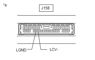
| NG | | REPLACE PARKING ASSIST ECU |
|
| 4. | CHECK PARKING ASSIST ECU (LCB+, LGND) |
| (a) Connect the J158 parking assist ECU connector. |
|
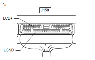
(b) Measure the voltage according to the value(s) in the table below.
Standard Voltage:
| Tester Connection | Switch Condition | Specified Condition |
|---|---|---|
| J158-12 (LCB+) - J158-35 (LGND) | Engine switch on (IG) | 5.5 to 7.05 V |
| NG | | REPLACE PARKING ASSIST ECU |
|
| 5. | CHECK SIDE TELEVISION CAMERA ASSEMBLY LH (LCV+, LGND) |
(a) Connect the N1 outer rear view mirror assembly LH connector.
(b) Using an oscilloscope, check the waveform of the side television camera assembly LH.
HINT:
A waterproof connector is used for the side television camera assembly LH. Therefore, inspect the waveform at the parking assist ECU with the connector connected.
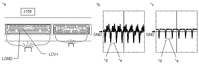
| *a | Component with harness connected (Parking Assist ECU) | *b | Waveform 1 |
| *c | Waveform 2 | *d | Synchronization Signal |
| *e | Video Waveform | - | - |
| Item | Content |
|---|---|
| Tester Connection | J158-10 (LCV+) - J158-35 (LGND) |
| Tool Setting | 200 mV/DIV., 50 μs./DIV. |
| Condition |
|
HINT:
- The video waveform changes according to the image sent by the side television camera assembly LH.
- The video waveform is constantly output when the engine switch is on (ACC).
OK:
Waveform is similar to that shown in illustration.
| OK | | REPLACE PARKING ASSIST ECU |
|
| 6. | CHECK SIDE TELEVISION CAMERA ASSEMBLY LH |
(a) Replace the side television camera assembly LH with a new or normally functioning one.
Click here
|
| 7. | CHECK FOR DTC |
(a) Clear the DTCs.
Chassis > Circumference Monitoring Camera Control Module > Clear DTCs(b) Check for DTCs.
Chassis > Circumference Monitoring Camera Control Module > Trouble CodesOK:
DTC C1686 is not output.
| Result | Proceed to |
|---|---|
| OK | A |
| NG (w/ Power Retract Mirror) | B |
| NG (w/o Power Retract Mirror) | C |
| A | | END (SIDE TELEVISION CAMERA ASSEMBLY LH WAS DEFECTIVE) |
| B | | REPLACE OUTER MIRROR RETRACTOR LH |
| C | | REPLACE OUTER REAR VIEW MIRROR ASSEMBLY LH |
 Side Camera Current Malfunction (C1684)
DESCRIPTION This DTC is stored if the parking assist ECU judges as a result of its self check that a synchronization problem is occurring in the image signal sent from the passenger side television ca ...
 Over Current Detected in Driver Side Camera (C1687)
DESCRIPTION This DTC is stored if the parking assist ECU judges as a result of its self check that a synchronization problem is occurring in the image signal sent from the driver side television camer ...
Other materials:
Lexus RX (RX 350L, RX450h) 2016-2026 Repair Manual > Automatic Transaxle System: Brake Switch "B" Circuit Short to Battery (P070312)
DESCRIPTION The purpose of the stop light switch signal circuit is to prevent the engine from stalling when the brakes are suddenly applied while driving in the lock-up condition. When the brake pedal is depressed, the stop light switch assembly sends a signal to the ECM. The ECM then cancels the op ...
Lexus RX (RX 350L, RX450h) 2016-2026 Repair Manual > Blind Spot Monitor System: Steering Angle Sensor (C1A47)
DESCRIPTION The blind spot monitor sensor receives steering angle signals from the steering angle sensor via CAN communication. DTC No. Detection Item DTC Detection Condition Trouble Area C1A47 Steering Angle Sensor A fail flag is transmitted from the steering angle sensor
Stee ...
Lexus RX (RX 350L, RX450h) 2016-{YEAR} Owners Manual
- For your information
- Pictorial index
- For safety and security
- Instrument cluster
- Operation of each component
- Driving
- Lexus Display Audio system
- Interior features
- Maintenance and care
- When trouble arises
- Vehicle specifications
- For owners
Lexus RX (RX 350L, RX450h) 2016-{YEAR} Repair Manual

0.0148