Lexus RX (RX 350L, RX450h) 2016-2026 Repair Manual: Over Current Detected in Driver Side Camera (C1687)
DESCRIPTION
This DTC is stored if the parking assist ECU judges as a result of its self check that a synchronization problem is occurring in the image signal sent from the driver side television camera assembly to the parking assist ECU.
| DTC No. | Detection Item | DTC Detection Condition | Trouble Area |
|---|---|---|---|
| C1687 | Over Current Detected in Driver Side Camera | Side camera current malfunction |
|
- *: w/ Power Retract Mirror
WIRING DIAGRAM

CAUTION / NOTICE / HINT
NOTICE:
-
When "!" is displayed on the multi-display assembly after the cable is disconnected from the negative (-) battery terminal, correct the steering angle neutral point.
Click here
.gif)
-
Depending on the parts that are replaced or operations that are performed during vehicle inspection or maintenance, calibration of other systems as well as the panoramic view monitor system may be needed.
Click here
PROCEDURE
| 1. | CHECK FOR DTC |
(a) Clear the DTCs.
Chassis > Circumference Monitoring Camera Control Module > Clear DTCs(b) Check for DTCs.
Chassis > Circumference Monitoring Camera Control Module > Trouble CodesOK:
DTC C1687 is not output.
| OK |  | USE SIMULATION METHOD TO CHECK |
|

| 2. | CHECK HARNESS AND CONNECTOR (PARKING ASSIST ECU - OUTER REAR VIEW MIRROR ASSEMBLY LH) |
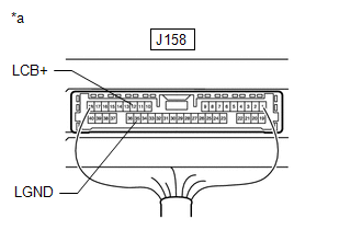
(a) Disconnect the J158 parking assist ECU connector.
(b) Disconnect the N1 outer rear view mirror assembly LH connector.
(c) Measure the resistance according to the value(s) in the table below.
Standard Resistance:
| Tester Connection | Condition | Specified Condition |
|---|---|---|
| J158-12 (LCB+) - N1-2 (LCB+) | Always | Below 1 Ω |
| J158-35 (LGND) - N1-1 (LGND) | Always | Below 1 Ω |
| J158-12 (LCB+) or N1-2 (LCB+) - Body ground | Always | 10 kΩ or higher |
| J158-35 (LGND) or N1-1 (LGND) - Body ground | Always | 10 kΩ or higher |
| NG | | REPAIR OR REPLACE HARNESS OR CONNECTOR |
|
| 3. | CHECK PARKING ASSIST ECU (LCB+, LGND) |
| (a) Connect the J158 parking assist ECU connector. |
|
(b) Measure the resistance according to the value(s) in the table below.
Standard Resistance:
| Tester Connection | Condition | Specified Condition |
|---|---|---|
| J158-35 (LGND) - Body ground | Always | Below 1 Ω |
(c) Measure the voltage according to the value(s) in the table below.
Standard Voltage:
| Tester Connection | Switch Condition | Specified Condition |
|---|---|---|
| J158-12 (LCB+) - J158-35 (LGND) | Engine switch on (IG) | 5.5 to 7.05 V |
| NG | | REPLACE PARKING ASSIST ECU |
|
| 4. | REPLACE SIDE TELEVISION CAMERA ASSEMBLY LH |
(a) Replace the side television camera assembly LH with a new or normally functioning one.
Click here
|
| 5. | CHECK FOR DTC |
(a) Clear the DTCs.
Chassis > Circumference Monitoring Camera Control Module > Clear DTCs(b) Check for DTCs.
Chassis > Circumference Monitoring Camera Control Module > Trouble CodesOK:
DTC C1687 is not output.
| Result | Proceed to |
|---|---|
| OK | A |
| NG (w/ Power Retract Mirror) | B |
| NG (w/o Power Retract Mirror) | C |
| A | | END (SIDE TELEVISION CAMERA ASSEMBLY LH WAS DEFECTIVE) |
| B | | REPLACE OUTER MIRROR RETRACTOR LH |
| C | | REPLACE OUTER REAR VIEW MIRROR ASSEMBLY LH |
 Driver Side Camera Video Sync Signal Malfunction (C1686)
DESCRIPTION This DTC is stored if the parking assist ECU judges as a result of its self check that a synchronization problem is occurring in the image signal sent from the driver side television camer ...
 Vehicle Information Unmatched (C168D)
DESCRIPTION This DTC is stored if the parking assist ECU judges as a result of its self check that the vehicle information received via CAN communication and the vehicle information stored in the park ...
Other materials:
Lexus RX (RX 350L, RX450h) 2016-2026 Repair Manual > Audio And Visual System (for 8 Inch Display): Portable Player cannot be Connected Manually/Automatically
CAUTION / NOTICE / HINT HINT: Some versions of "Bluetooth" compatible audio players may not function properly, or the functions may be limited using the radio receiver assembly, even if the portable audio player itself can play files. Click here PROCEDURE 1. CHECK CONNECTED DEVICE SETTINGS ...
Lexus RX (RX 350L, RX450h) 2016-2026 Repair Manual > Sfi System: Problem Symptoms Table
PROBLEM SYMPTOMS TABLE HINT:
Use the table below to help determine the cause of problem symptoms. If multiple suspected areas are listed, the potential causes of the symptoms are listed in order of probability in the "Suspected Area" column of the table. Check each symptom by checking the suspect ...
Lexus RX (RX 350L, RX450h) 2016-{YEAR} Owners Manual
- For your information
- Pictorial index
- For safety and security
- Instrument cluster
- Operation of each component
- Driving
- Lexus Display Audio system
- Interior features
- Maintenance and care
- When trouble arises
- Vehicle specifications
- For owners
Lexus RX (RX 350L, RX450h) 2016-{YEAR} Repair Manual

0.0099