Lexus RX (RX 350L, RX450h) 2016-2026 Repair Manual: Reverse Signal Circuit
DESCRIPTION
The multi-display assembly receives a reverse signal from the park/neutral position switch assembly*1 or clearance warning ECU assembly*2.
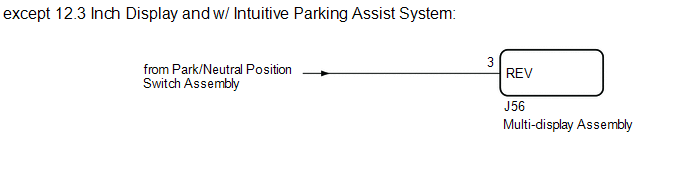
*1: except 12.3 Inch Display and w/ Intuitive Parking Assist System
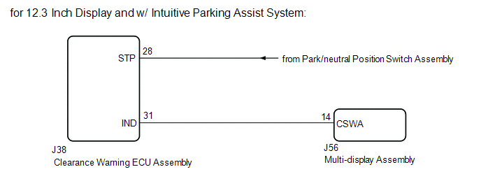
*2: for 12.3 Inch Display and w/ Intuitive Parking Assist System
WIRING DIAGRAM
CAUTION / NOTICE / HINT
NOTICE:
-
When "!" mark is displayed on the multi-display assembly after disconnecting the cable from the negative (-) battery terminal, correct the steering angle neutral point.
Click here
.gif)
-
Depending on the parts that are replaced or operations that are performed during vehicle inspection or maintenance, calibration of other systems as well as the parking assist monitor system may be needed.
Click here
PROCEDURE
| 1. | CHECK BACK-UP LIGHT |
(a) Check that the back-up light comes on.
OK:
The back-up light comes on.
| Result | Proceed to |
|---|---|
| OK (except 12.3 Inch Display and w/ Intuitive Parking Assist System) | A |
| OK (for 12.3 Inch Display and w/ Intuitive Parking Assist System) | B |
| NG | C |
| B | .gif) | GO TO STEP 3 |
| C | | GO TO LIGHTING SYSTEM (EXT) |
|
.gif)
| 2. | CHECK HARNESS AND CONNECTOR (REVERSE SIGNAL) |
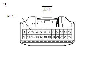
| (a) Disconnect the J56 multi-display assembly connector. |
|
(b) Measure the voltage according to the value(s) in the table below.
Standard Voltage:
| Tester Connection | Condition | Specified Condition |
|---|---|---|
| J56-3 (REV) - Body ground | Engine switch on (IG) Shift position in R | 11 to 14 V |
| J56-3 (REV) - Body ground | Engine switch on (IG) Shift position not in R | Below 1 V |
| OK | | PROCEED TO NEXT SUSPECTED AREA SHOWN IN PROBLEM SYMPTOMS TABLE |
| NG | | REPAIR OR REPLACE HARNESS OR CONNECTOR |
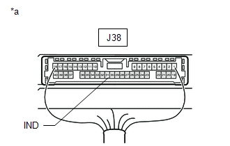
| 3. | CHECK HARNESS AND CONNECTOR (REVERSE SIGNAL) |
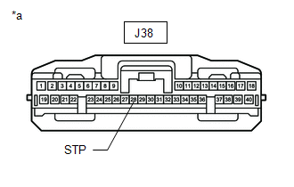
| (a) Disconnect the J38 clearance warning ECU assembly connector. |
|
(b) Measure the voltage according to the value(s) in the table below.
Standard Voltage:
| Tester Connection | Condition | Specified Condition |
|---|---|---|
| J38-28 (STP) - Body ground | Engine switch on (IG) Shift position in R | 11 to 14 V |
| J38-28 (STP) - Body ground | Engine switch on (IG) Shift position not in R | Below 1 V |
| NG | | REPAIR OR REPLACE HARNESS OR CONNECTOR |
|
| 4. | CHECK HARNESS AND CONNECTOR (CLEARANCE WARNING ECU ASSEMBLY - MULTI-DISPLAY ASSEMBLY) |
(a) Disconnect the J38 clearance warning ECU assembly connector.
(b) Disconnect the J56 multi-display assembly connector.
(c) Measure the resistance according to the value(s) in the table below.
Standard Resistance:
| Tester Connection | Condition | Specified Condition |
|---|---|---|
| J38-31 (IND) - J56-14 (CSWA) | Always | Below 1 Ω |
| J38-31 (IND) or J56-14 (CSWA) - Body ground | Always | 10 kΩ or higher |
| NG | | REPAIR OR REPLACE HARNESS OR CONNECTOR |
|
| 5. | INSPECT CLEARANCE WARNING ECU ASSEMBLY |
| (a) Disconnect the multi-display assembly connector. |
|
(b) Measure the voltage according to the value(s) in the table below.
Standard Voltage:
| Tester Connection | Condition | Specified Condition |
|---|---|---|
| J38-31 (IND) - Body ground | Engine switch on (IG) Shift position in R | Below 3 V |
| J38-31 (IND) - Body ground | Engine switch on (IG) Shift position not in R | 8 V or higher |
| OK | | PROCEED TO NEXT SUSPECTED AREA SHOWN IN PROBLEM SYMPTOMS TABLE |
| NG | | REPLACE CLEARANCE WARNING ECU ASSEMBLY |
 Image from Camera for Parking Assist Monitor is Abnormal
DESCRIPTION The video signal from the rear television camera assembly is transmitted to the multi-display assembly. WIRING DIAGRAM CAUTION / NOTICE / HINT NOTICE:
When "!" mark is displayed on the ...

Other materials:
Lexus RX (RX 350L, RX450h) 2016-2026 Repair Manual > Power Back Door System (w/ Outside Door Control Switch): Terminals Of Ecu
TERMINALS OF ECU CHECK MULTIPLEX NETWORK DOOR ECU (a) Disconnect the Z16 and Z17 multiplex network door ECU connectors. (b) Measure the voltage and resistance according to the value(s) in the table below. HINT: Measure the values on the wire harness side with the connector disconnected. Terminal ...
Lexus RX (RX 350L, RX450h) 2016-2026 Repair Manual > Washer Nozzle(for Front Side): Adjustment
ADJUSTMENT PROCEDURE 1. REMOVE WASHER NOZZLE SUB-ASSEMBLY Click here 2. ADJUST WASHER NOZZLE SUB-ASSEMBLY (a) Select a washer nozzle sub-assembly so that the position that the washer fluid hits the windshield will be within the standard area. Replace the washer nozzle sub-assembly with the selecte ...
Lexus RX (RX 350L, RX450h) 2016-{YEAR} Owners Manual
- For your information
- Pictorial index
- For safety and security
- Instrument cluster
- Operation of each component
- Driving
- Lexus Display Audio system
- Interior features
- Maintenance and care
- When trouble arises
- Vehicle specifications
- For owners
Lexus RX (RX 350L, RX450h) 2016-{YEAR} Repair Manual

0.0123