Lexus RX (RX 350L, RX450h) 2016-2026 Repair Manual: Removal
REMOVAL
CAUTION / NOTICE / HINT
The necessary procedures (adjustment, calibration, initialization, or registration) that must be performed after parts are removed, installed, or replaced during brake actuator assembly removal/installation are shown below.
Necessary Procedure After Parts Removed/Installed/Replaced| Replacement Part or Procedure | Necessary Procedures | Effects/Inoperative when not Performed | Link |
|---|---|---|---|
| Disconnect cable from negative battery terminal | Memorize steering angle neutral point | Lane control system | |
| Pre-collision system | |||
| Intelligent clearance sonar system | |||
| Lighting system (w/ Automatic Headlight Beam Level Control System) | | ||
| Parking assist monitor system | | ||
| Panoramic view monitor system | | ||
| Initialize back door lock | Power door lock control system | | |
| Reset back door close position | Power back door system (w/ Outside Door Control Switch) | | |
| Replacement of brake actuator assembly | Operate the electric parking brake switch assembly | Parking brake indicator light (red) blinks when the engine switch is first turned on (IG) | |
| Calibration |
| |
PROCEDURE
1. PRECAUTION
NOTICE:
After turning the engine switch off, waiting time may be required before disconnecting the cable from the negative (-) battery terminal. Therefore, make sure to read the disconnecting the cable from the negative (-) battery terminal notices before proceeding with work.
Click here .gif)
2. DISCONNECT CABLE FROM NEGATIVE BATTERY TERMINAL
NOTICE:
When disconnecting the cable, some systems need to be initialized after the cable is reconnected.
Click here
3. DRAIN BRAKE FLUID
NOTICE:
If brake fluid leaks onto any painted surface, immediately wash it off.
4. REMOVE BRAKE ACTUATOR WITH BRACKET
(a) Release the lock lever and disconnect the connector from the brake actuator assembly.
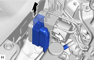
 | Release the lock lever |
 | Disconnect the connector |
NOTICE:
Be careful not to allow any brake fluid to enter the connector.
| (b) Use tags or make a memo to identify the places to reconnect the brake lines. |
|
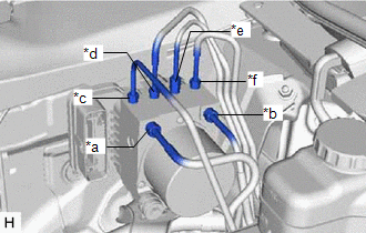
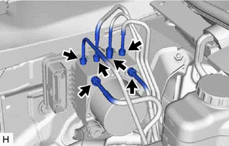
| (c) Using a union nut wrench, disconnect the 6 brake lines from the brake actuator assembly. |
|
| (d) Remove the bolt, 2 nuts and brake actuator with bracket. NOTICE:
HINT: Remove the brake actuator with bracket while avoiding the brake lines. |
|
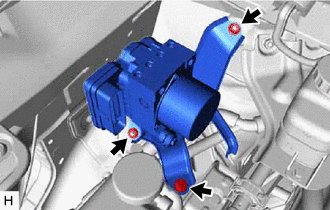
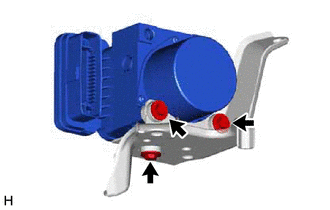
5. REMOVE BRAKE ACTUATOR ASSEMBLY
| (a) Remove the 3 bolts and brake actuator assembly from the brake actuator bracket assembly. NOTICE: Do not hold the brake actuator assembly by the connector. |
|
 On-vehicle Inspection
ON-VEHICLE INSPECTION PROCEDURE 1. CONNECT TECHSTREAM (a) Connect the Techstream to the DLC3 with the engine switch off. (b) Start the engine and run it at idle. (c) Turn the Techstream on. (d) Enter ...
 Installation
INSTALLATION CAUTION / NOTICE / HINT HINT: The parking brake indicator light blinks (red) when the engine switch is turned on after replacing the brake actuator assembly. Operate the electric parking ...
Other materials:
Lexus RX (RX 350L, RX450h) 2016-2026 Repair Manual > 2gr-fks (starting): Starting System
Parts LocationPARTS LOCATION ILLUSTRATION *1 STARTER ASSEMBLY *2 ECM *3 ENGINE ROOM RELAY BLOCK ASSEMBLY - ST RELAY - ST NO. 1 FUSE *4 PARK/NEUTRAL POSITION SWITCH ASSEMBLY ILLUSTRATION *1 ENGINE SWITCH *2 CERTIFICATION ECU (SMART KEY ECU ASSEMBLY) System DiagramS ...
Lexus RX (RX 350L, RX450h) 2016-2026 Repair Manual > Parking Assist Monitor System: Parts Location
PARTS LOCATION ILLUSTRATION *A w/o Rear No. 2 Seat - - *1 PARK/NEUTRAL POSITION SWITCH ASSEMBLY *2 ECM *3 BRAKE ACTUATOR ASSEMBLY - SKID CONTROL ECU *4 ENGINE ROOM RELAY BLOCK AND JUNCTION BLOCK ASSEMBLY - ECU-IG1 NO. 5 FUSE *5 REAR TELEVISION CAMERA ASSEMBLY *6 ...
Lexus RX (RX 350L, RX450h) 2016-{YEAR} Owners Manual
- For your information
- Pictorial index
- For safety and security
- Instrument cluster
- Operation of each component
- Driving
- Lexus Display Audio system
- Interior features
- Maintenance and care
- When trouble arises
- Vehicle specifications
- For owners
Lexus RX (RX 350L, RX450h) 2016-{YEAR} Repair Manual

0.0099