Lexus RX (RX 350L, RX450h) 2016-2025 Repair Manual: Brake System Control Module "A" System Voltage System Voltage Low (C137BA2)
DESCRIPTION
If a malfunction is detected in the power supply circuit, the skid control ECU (brake actuator assembly) stores this DTC and the fail-safe function prohibits ABS operation.
This DTC is stored when the +BS terminal voltage meets one of the DTC detection conditions due to a malfunction in the power supply or charging circuit such as the battery or alternator circuit, etc.
The DTC is cleared when the +BS terminal voltage returns to normal.
| DTC No. | Detection Item | DTC Detection Condition | Trouble Area |
|---|---|---|---|
| C137BA2 | Brake System Control Module "A" System Voltage System Voltage Low | Any of the following is detected:
|
|
| Vehicle Condition | ||||||
|---|---|---|---|---|---|---|
| Pattern 1 | Pattern 2 | Pattern 3 | Pattern 4 | Pattern 5 | ||
| Diagnosis Condition | When the +BS terminal voltage is below 9.5 V | ○ | - | - | - | ○ |
| The +BS terminal voltage is below 9.5 V for 3 seconds or more and the vehicle is driven at 3 km/h (2 mph) or more | - | ○ | - | - | - | |
| When the +BS terminal voltage is 9.5 V or higher and the vehicle speed exceeds 15 km/h (9 mph) | - | - | ○ | - | - | |
| When the +BS terminal voltage is below 9.5 V and the solenoid relay is ON | - | - | - | ○ | - | |
| Malfunction Status | The power source voltage for all speed sensors is continuously low | ○ | - | - | - | - |
| The +BS terminal voltage is below 9.5 V continuously | - | ○ | - | - | - | |
| The IG1 terminal voltage is 10 V or less continuously | - | - | ○ | - | - | |
| The relay contact is OFF continuously | - | - | - | ○ | - | |
| Motor fail-safe relay overcurrent continues | - | - | - | - | ○ | |
| Detection Time | 60 seconds or more | 7 seconds or more | 60 seconds or more | 1.22 seconds or more | 1.05 seconds or more | |
| Number of Trips | 1 trip | 1 trip | 1 trip | 1 trip | 1 trip | |
HINT:
DTC will be output when conditions for any of the patterns in the table above are met.
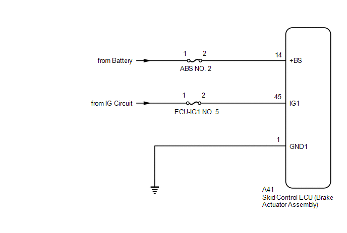
WIRING DIAGRAM
CAUTION / NOTICE / HINT
NOTICE:
- Inspect the fuses for circuits related to this system before performing the following procedure.
-
After replacing the skid control ECU (brake actuator assembly), perform "Calibration".
Click here
.gif)
PROCEDURE
| 1. | CHECK BATTERY |
(a) Check the battery voltage.
Standard Voltage:
| Tester Connection | Condition | Specified Condition |
|---|---|---|
| Positive (+) terminal - Negative (-) terminal | Always | 11 to 14 V |
| NG | .gif) | CHECK OR REPLACE CHARGING SYSTEM OR BATTERY |
|
.gif)
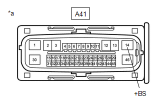
| 2. | CHECK HARNESS AND CONNECTOR (+BS TERMINAL) |
| (a) Make sure that there is no looseness at the locking part and the connecting part of the connectors. OK: The connector is securely connected. |
|
(b) Disconnect the A41 skid control ECU (brake actuator assembly) connector.
(c) Check both the connector case and the terminals for deformation and corrosion.
OK:
No deformation or corrosion.
(d) Measure the voltage according to the value(s) in the table below.
Standard Voltage:
| Tester Connection | Condition | Specified Condition |
|---|---|---|
| A41-14 (+BS) - Body ground | Always | 11 to 14 V |
| NG | | REPAIR OR REPLACE HARNESS OR CONNECTOR (+BS CIRCUIT) |
|
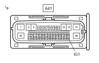
| 3. | CHECK HARNESS AND CONNECTOR (IG1 TERMINAL) |
| (a) Turn the engine switch on (IG). |
|
(b) Measure the voltage according to the value(s) in the table below.
Standard Voltage:
| Tester Connection | Condition | Specified Condition |
|---|---|---|
| A41-45 (IG1) - Body ground | Engine switch on (IG) | 11 to 14 V |
| NG | | REPAIR OR REPLACE HARNESS OR CONNECTOR |
|
| 4. | CHECK HARNESS AND CONNECTOR (GND1 TERMINAL) |
(a) Turn the engine switch off.
(b) Measure the resistance according to the value(s) in the table below.
Standard Resistance:
| Tester Connection | Condition | Specified Condition |
|---|---|---|
| A41-1 (GND1) - Body ground | 1 minute or more after disconnecting the cable from the negative (-) battery terminal | Below 1 Ω |
| NG | | REPAIR OR REPLACE HARNESS OR CONNECTOR |
|
| 5. | CLEAR DTC |
(a) Reconnect the A41 skid control ECU (brake actuator assembly) connector.
(b) Connect the Techstream to the DLC3.
(c) Turn the engine switch on (IG).
(d) Operate the Techstream to clear the codes. Enter the following menus: Chassis / Brake/EPB / Trouble Codes.
Chassis > Brake/EPB > Clear DTCs(e) Press the DTC clear button.
(f) Turn the engine switch off.
|
| 6. | RECONFIRM DTC |
(a) Start the engine.
(b) Perform a road test.
(c) Read the DTCs following the prompts on the Techstream. Enter the following menus: Chassis / Brake/EPB / Trouble Codes.
Chassis > Brake/EPB > Trouble Codes(d) Check if the same DTC is output.
| Result | Proceed to |
|---|---|
| DTC C137BA2 is not output. | A |
| DTC C137BA2 is output. | B |
| A | | USE SIMULATION METHOD TO CHECK |
| B | | REPLACE BRAKE ACTUATOR ASSEMBLY |
 Yaw Rate Sensor Signal Compare Failure (C124F62)
DESCRIPTION for Optitron Meter Type:
This DTC is stored when the skid control ECU (brake actuator assembly) detects improper installation of the yaw rate sensor (airbag sensor assembly) or an abnor ...
 Brake System Control Module "A" System Voltage System Voltage High (C137BA3)
DESCRIPTION If a malfunction is detected in the power supply circuit, the skid control ECU (brake actuator assembly) stores this DTC and the fail-safe function prohibits ABS operation. This DTC is sto ...
Other materials:
Lexus RX (RX 350L, RX450h) 2016-2025 Repair Manual > Propeller Shaft Assembly: Disassembly
DISASSEMBLY CAUTION / NOTICE / HINT NOTICE:
When using a vise, place aluminum plates between the part and vise.
When using a vise, do not overtighten it.
PROCEDURE 1. REMOVE PROPELLER SHAFT ASSEMBLY (a) Place matchmarks on the propeller shaft assembly and universal joint flange. NOTICE: D ...
Lexus RX (RX 350L, RX450h) 2016-2025 Repair Manual > Power Mirror Control System (w/ Memory): System Diagram
SYSTEM DIAGRAM Communication Table Sender Receiver Signal Line Air Conditioning Amplifier Assembly Main Body ECU (Multiplex Network Body ECU) Mirror heater drive request signal CAN Main Body ECU (Multiplex Network Body ECU) Outer Mirror Control ECU Assembly
IG sign ...
Lexus RX (RX 350L, RX450h) 2016-{YEAR} Owners Manual
- For your information
- Pictorial index
- For safety and security
- Instrument cluster
- Operation of each component
- Driving
- Lexus Display Audio system
- Interior features
- Maintenance and care
- When trouble arises
- Vehicle specifications
- For owners
Lexus RX (RX 350L, RX450h) 2016-{YEAR} Repair Manual

0.0124