Lexus RX (RX 350L, RX450h) 2016-2026 Repair Manual: Disassembly
DISASSEMBLY
CAUTION / NOTICE / HINT
NOTICE:
- When using a vise, place aluminum plates between the part and vise.
- When using a vise, do not overtighten it.
PROCEDURE
1. REMOVE PROPELLER SHAFT ASSEMBLY
| (a) Place matchmarks on the propeller shaft assembly and universal joint flange. NOTICE: Do not use a punch for the marks. |
|
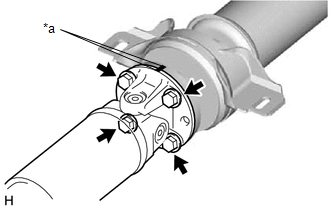
(b) Remove the 4 nuts, 4 bolts, 4 washers and propeller shaft assembly.
2. REMOVE INTERMEDIATE SHAFT ASSEMBLY
| (a) Place matchmarks on the rear propeller shaft assembly and universal joint flange. NOTICE: Do not use a punch for the marks. |
|
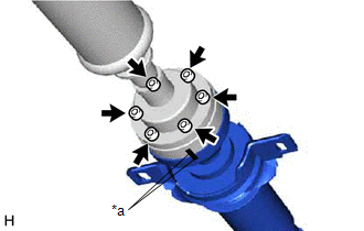
(b) Using a 6 mm hexagon socket wrench, remove the 6 cross groove joint set bolts, 2 universal joint washers and intermediate shaft assembly.
3. REMOVE CENTER NO. 2 SUPPORT BEARING ASSEMBLY (for Rear Side)
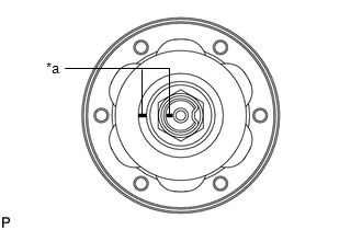
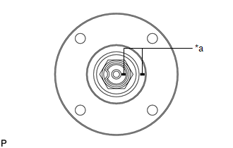
| (a) Place matchmarks on the intermediate shaft assembly and universal joint flange. NOTICE: Do not use a punch for the marks. |
|
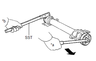
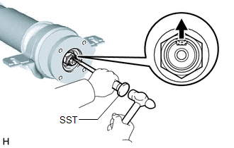
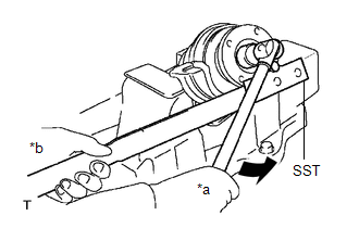
| (b) Using SST and a hammer, release the staked part of the nut. SST: 09930-00010 NOTICE: Release the staked part of the nut completely, otherwise the threads of the intermediate shaft assembly may be damaged. |
|
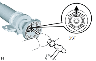
| (c) Using SST to hold the universal joint flange, remove the nut and washer. SST: 09330-00021 |
|
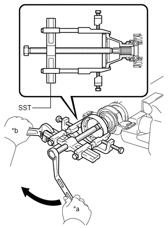
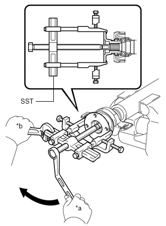
| (d) Using SST, remove the universal joint flange from the intermediate shaft assembly. SST: 09950-40011 09951-04020 09952-04010 09953-04030 09954-04010 09955-04061 09957-04010 09958-04011 NOTICE:
|
|
(e) Remove the center No. 2 support bearing assembly and washer from the intermediate shaft assembly.
4. REMOVE CENTER NO. 2 SUPPORT BEARING ASSEMBLY (for Front Side)
| (a) Place matchmarks on the intermediate shaft assembly and universal joint flange. NOTICE: Do not use a punch for the marks. |
|
| (b) Using SST and a hammer, release the staked part of the nut. SST: 09930-00010 NOTICE: Release the staked part of the nut completely, otherwise the threads of the intermediate shaft assembly may be damaged. |
|
| (c) Using SST to hold the universal joint flange, remove the nut and washer. SST: 09330-00021 |
|
| (d) Using SST, remove the universal joint flange from the intermediate shaft assembly. SST: 09950-40011 09951-04020 09952-04010 09953-04030 09954-04010 09955-04061 09957-04010 09958-04011 NOTICE:
|
|
(e) Remove the center No. 2 support bearing assembly and washer from the intermediate shaft assembly.
 Components
COMPONENTS ILLUSTRATION *A for Front Side *B for Rear Side *C for TMC Made *D for TMMC Made *E for Type A *F for Type B *1 FRONT CENTER FLOOR COVER *2 FRONT FLO ...
 Removal
REMOVAL PROCEDURE 1. REMOVE NO. 2 ENGINE UNDER COVER Click here 2. REMOVE FRONT FLOOR COVER LH Click here 3. REMOVE FRONT CENTER FLOOR COVER for TMC Made: Click here for TMMC Made: Click he ...
Other materials:
Lexus RX (RX 350L, RX450h) 2016-2026 Repair Manual > Parking Assist Monitor System: Image from Camera for Parking Assist Monitor is Abnormal
DESCRIPTION The video signal from the rear television camera assembly is transmitted to the multi-display assembly. WIRING DIAGRAM CAUTION / NOTICE / HINT NOTICE:
When "!" mark is displayed on the multi-display assembly after disconnecting the cable from the negative (-) battery terminal, correc ...
Lexus RX (RX 350L, RX450h) 2016-2026 Repair Manual > Dynamic Radar Cruise Control System: Cruise Control System Internal Failure (P057504,P057549)
DESCRIPTION When the ECM detects an internal malfunction, DTC P057504 or P057549 is stored. DTC No. Detection Item DTC Detection Condition Trouble Area MIL DTC Output from P057504 Cruise Control System Internal Failure When the dynamic radar cruise control system is operating, t ...
Lexus RX (RX 350L, RX450h) 2016-{YEAR} Owners Manual
- For your information
- Pictorial index
- For safety and security
- Instrument cluster
- Operation of each component
- Driving
- Lexus Display Audio system
- Interior features
- Maintenance and care
- When trouble arises
- Vehicle specifications
- For owners
Lexus RX (RX 350L, RX450h) 2016-{YEAR} Repair Manual

0.011