Lexus RX (RX 350L, RX450h) 2016-2026 Repair Manual: Voice Recognition Microphone Disconnected (B1579)
DESCRIPTION
The radio receiver assembly and telephone microphone assembly are connected to each other using the microphone connection detection signal lines.
This DTC is stored when a microphone connection detection signal line is disconnected.
| DTC No. | Detection Item | DTC Detection Condition | Trouble Area |
|---|---|---|---|
| B1579 | Voice Recognition Microphone Disconnected | Microphone signal is lost. |
|
- *: w/ Manual (SOS) Switch
WIRING DIAGRAM
w/ Manual (SOS) Switch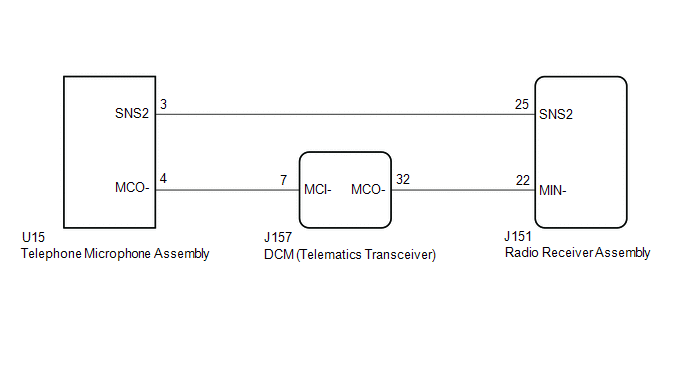 w/o Manual (SOS) Switch
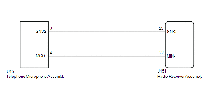
CAUTION / NOTICE / HINT
NOTICE:
-
Depending on the parts that are replaced during vehicle inspection or maintenance, performing initialization, registration or calibration may be needed. Refer to Precaution for Audio and Visual System.
Click here
.gif)
-
Before replacing the DCM (telematics transceiver), refer to Registration.
Click here
PROCEDURE
| 1. | INSPECT RADIO RECEIVER ASSEMBLY |
| (a) Measure the resistance according to the value(s) in the table below. Standard Resistance:
|
|
| NG |  | REPLACE RADIO RECEIVER ASSEMBLY |
|

| 2. | CHECK MODEL |
(a) Choose the model to be inspected.
| Result | Proceed to |
|---|---|
| w/ Manual (SOS) Switch | A |
| w/o Manual (SOS) Switch | B |
| B | | GO TO STEP 8 |
|
| 3. | CHECK HARNESS AND CONNECTOR (DCM (TELEMATICS TRANSCEIVER) - TELEPHONE MICROPHONE ASSEMBLY) |
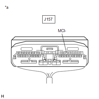
(a) Disconnect the J157 DCM (telematics transceiver) connector.
(b) Disconnect the U15 telephone microphone assembly connector.
(c) Measure the resistance according to the value(s) in the table below.
Standard Resistance:
| Tester Connection | Condition | Specified Condition |
|---|---|---|
| J157-7 (MCI-) - U15-4 (MCO-) | Always | Below 1 Ω |
| J157-7 (MCI-) or U15-4 (MCO-) - Body ground | Always | 10 kΩ or higher |
| NG | | REPAIR OR REPLACE HARNESS OR CONNECTOR |
|
| 4. | CHECK HARNESS AND CONNECTOR (RADIO RECEIVER ASSEMBLY - DCM (TELEMATICS TRANSCEIVER)) |
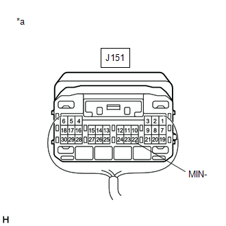
(a) Disconnect the J151 radio receiver assembly connector.
(b) Disconnect the J157 DCM (telematics transceiver) connector.
(c) Measure the resistance according to the value(s) in the table below.
Standard Resistance:
| Tester Connection | Condition | Specified Condition |
|---|---|---|
| J151-22 (MIN-) - J157-32 (MCO-) | Always | Below 1 Ω |
| J151-22 (MIN-) or J157-32 (MCO-) - Body ground | Always | 10 kΩ or higher |
| NG | | REPAIR OR REPLACE HARNESS OR CONNECTOR |
|
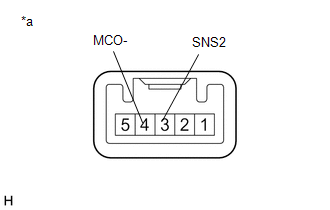
| 5. | CHECK HARNESS AND CONNECTOR (RADIO RECEIVER ASSEMBLY - TELEPHONE MICROPHONE ASSEMBLY) |
(a) Disconnect the J151 radio receiver assembly connector.
(b) Disconnect the U15 telephone microphone assembly connector.
(c) Measure the resistance according to the value(s) in the table below.
Standard Resistance:
| Tester Connection | Condition | Specified Condition |
|---|---|---|
| J151-25 (SNS2) - U15-3 (SNS2) | Always | Below 1 Ω |
| J151-25 (SNS2) or U15-3 (SNS2) - Body ground | Always | 10 kΩ or higher |
| NG | | REPAIR OR REPLACE HARNESS OR CONNECTOR |
|
| 6. | INSPECT DCM (TELEMATICS TRANSCEIVER) |
(a) Reconnect the J157 DCM (telematics transceiver) connector.
(b) Reconnect the J151 radio receiver assembly connector.
| (c) Measure the resistance according to the value(s) in the table below. Standard Resistance:
|
|
(d) Proceed to the next step based on the inspection result.
| NG | | REPLACE DCM (TELEMATICS TRANSCEIVER) |
|
| 7. | INSPECT TELEPHONE MICROPHONE ASSEMBLY |
(a) Remove the telephone microphone assembly.
Click here
| (b) Measure the resistance according to the value(s) in the table below. Standard Resistance:
|
|
| OK | | REPLACE RADIO RECEIVER ASSEMBLY |
| NG | | REPLACE TELEPHONE MICROPHONE ASSEMBLY |
| 8. | CHECK HARNESS AND CONNECTOR (RADIO RECEIVER ASSEMBLY - TELEPHONE MICROPHONE ASSEMBLY) |
(a) Disconnect the J151 radio receiver assembly connector.
(b) Disconnect the U15 telephone microphone assembly connector.
(c) Measure the resistance according to the value(s) in the table below.
Standard Resistance:
| Tester Connection | Condition | Specified Condition |
|---|---|---|
| J151-25 (SNS2) - U15-3 (SNS2) | Always | Below 1 Ω |
| J151-22 (MIN-) - U15-4 (MCO-) | Always | Below 1 Ω |
| J151-25 (SNS2) or U15-3 (SNS2) - Body ground | Always | 10 kΩ or higher |
| J151-22 (MIN-) or U15-4 (MCO-) - Body ground | Always | 10 kΩ or higher |
| NG | | REPAIR OR REPLACE HARNESS OR CONNECTOR |
|
| 9. | INSPECT TELEPHONE MICROPHONE ASSEMBLY |
(a) Remove the telephone microphone assembly.
Click here
| (b) Measure the resistance according to the value(s) in the table below. Standard Resistance:
|
|
| OK | | REPLACE RADIO RECEIVER ASSEMBLY |
| NG | | REPLACE TELEPHONE MICROPHONE ASSEMBLY |
 GVIF Disconnected (from EMV/MM Integrated Device to Multi Display) (B1575)
DESCRIPTION The radio receiver assembly and multi-display assembly are connected via video signal (digital) lines. This DTC is stored when a video signal (digital) line is disconnected. DTC No. D ...
 USB Device Malfunction (B1585)
DESCRIPTION This DTC is stored when a malfunction occurs in a connected device. DTC No. Detection Item DTC Detection Condition Trouble Area B1585 USB Device Malfunction When any of th ...
Other materials:
Lexus RX (RX 350L, RX450h) 2016-2026 Repair Manual > Charging System: Dtc Check / Clear
DTC CHECK / CLEAR CHECK DTC (a) Connect the Techstream to the DLC3. (b) Turn the engine switch on (IG). (c) Turn the Techstream on. (d) Enter the following menus: Powertrain / Engine / Trouble Codes. (e) Check for DTCs, and then write them down. (f) Check the details of the DTCs. Click here Power ...
Lexus RX (RX 350L, RX450h) 2016-2026 Repair Manual > Vacuum Warning Switch: Removal
REMOVAL PROCEDURE 1. REMOVE FRONT WIPER MOTOR AND LINK ASSEMBLY Click here 2. REMOVE OUTER COWL TOP PANEL SUB-ASSEMBLY Click here 3. REMOVE VACUUM WARNING SWITCH ASSEMBLY (for TMC Made) (a) Disconnect the connector from the vacuum warning switch assembly. (b) Remove the vacuum w ...
Lexus RX (RX 350L, RX450h) 2016-{YEAR} Owners Manual
- For your information
- Pictorial index
- For safety and security
- Instrument cluster
- Operation of each component
- Driving
- Lexus Display Audio system
- Interior features
- Maintenance and care
- When trouble arises
- Vehicle specifications
- For owners
Lexus RX (RX 350L, RX450h) 2016-{YEAR} Repair Manual

0.0089