Lexus RX (RX 350L, RX450h) 2016-2026 Repair Manual: System Description
SYSTEM DESCRIPTION
GENERAL
(a) The blind spot monitor system has a blind spot monitor function and RCTA function.
(1) Blind spot monitor function
-
The blind spot monitor function is a function that assists the driver when changing lanes.
This function uses quasi-millimeter wave radar to detect vehicles that are traveling in adjacent lanes in the areas that are not visible using the outer rear view mirror assemblies (blind spots) and vehicles that are approaching rapidly from up to 60 m behind this vehicle in the areas that are not visible using the outer rear view mirror assemblies (blind spots).
The function advises the driver of the existence of a vehicle by illuminating the outer rear view mirror indicator on the outer rear view mirror assembly.
- If the turn signal switch is operated while the outer rear view mirror indicator on an outer rear view mirror assembly is illuminated, the indicator starts blinking to give additional warning to the driver.
(2) RCTA function
- The RCTA function is a function that informs the driver a vehicle is approaching from the left or the right at the rear of the vehicle. The function uses quasi-millimeter wave radar to detect the position and relative speed of other vehicles. When the function determines that a vehicle is approaching this vehicle, this function informs the driver using the outer rear view mirror indicators and blind spot monitor buzzer.
FUNCTION OF COMPONENTS
| Component | Function |
|---|---|
| Blind Spot Monitor Sensor |
|
| Outer Rear View Mirror Assembly
| Turns on or blinks the indicator based on a signal from the blind spot monitor sensor. |
| Steering Pad Switch Assembly | Enables, disables or cuts off the operation of the blind spot monitor system by transmitting switch operation signals to the combination meter assembly. |
| RCTA Buzzer (Blind Spot Monitor Buzzer) | Sounds based on a signal from the blind spot monitor sensor. |
| Combination Meter Assembly
|
|
| Main Body ECU (Multiplex Network Body ECU) | Transmits the destination information and the dimmer signal to the blind spot monitor sensor via CAN communication. |
| Skid Control ECU | Transmits the vehicle speed signal to the blind spot monitor sensor via CAN communication. |
| ECM | Transmits the shift position signal (R) to the blind spot monitor sensor via CAN communication. |
| Steering Sensor | Detects the angle of the steering wheel and transmits the resulting signals to the blind spot monitor sensor via CAN communication. |
| Transmits the yaw rate signal to the blind spot monitor sensor via CAN communication. |
| Parking Assist ECU*3*4 | Receives the blind spot monitor sensor information via CAN communication and sends it to the multi-display assembly. |
| Radio Receiver Assembly |
|
| Multi-display Assembly |
|
- *1: for Optitron Meter Type
- *2: for TFT Meter Type
- *3: w/ Panoramic View Monitor System
OPERATION DESCRIPTION
(a) Operation description of the blind spot monitor function
(1) Operation conditions:
- The blind spot monitor system is on.
- The shift lever is in any position other than R.
- Vehicle speed is more than approximately 16 km/h (10 mph).
(2) Conditions in which a sensor can detect a vehicle
The blind spot monitor function indicates detection of a vehicle in the detection area when either condition is met:
- When a vehicle is detected in an adjacent lane overtaking this vehicle.
- When a vehicle is detected entering the detection area because it changed lanes.
HINT:
The greater the difference in speed between the vehicle and the detected vehicle is, the farther away the other vehicle will be when the notification is given.
(3) Detection area
Vehicles in the following areas can be detected:
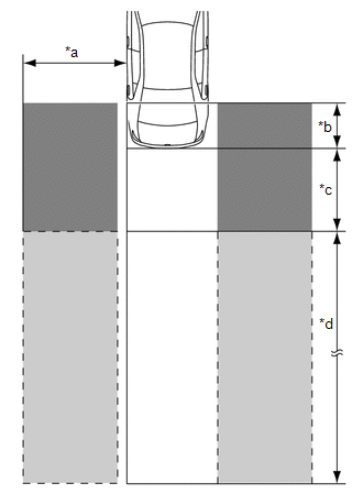
| *a | Within Approx. 3.5 m (11.48 ft) from Side of Vehicle |
| *b | Within Approx. 1 m (3.28 ft) Forward of Rear Bumper |
| *c | Within Approx. 3 m (9.84 ft) Behind Rear Bumper |
| *d | Within Approx. 3 m (9.84 ft) to 60 m (196.86 ft) from Rear Bumper |
.png) | Detection Area (for Vehicle in Blind Spot) |
 | Detection Area (for Rapidly Approaching Vehicle from Behind) |
(b) Operation description of the RCTA function
(1) Operation conditions:
- The blind spot monitor system is on.
- The shift lever is in R.
- The vehicle speed is less than approximately 8 km/h (5 mph).
(2) Conditions in which a sensor can detect a vehicle
The RCTA function indicates detection of a vehicle in the detection area when both conditions are met:
- A vehicle is approaching from the right or left at the rear of the vehicle.
- The vehicle speed is approximately 8 km/h (5 mph) to 28 km/h (17 mph).
(3) Detection area
Vehicles in the following areas can be detected:
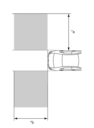
| *a | Within Approx. 5.5 to 20 m (18.05 to 65.62 ft) from Side of Vehicle (detection area changes according to vehicle speed) |
| *b | Within Approx. 6 m (19.69 ft) Behind Rear Bumper |
| | Detection Area |
OPERATION OF OUTER REAR VIEW MIRROR INDICATOR AND RCTA BUZZER (BLIND SPOT MONITOR BUZZER)
(a) Initial check
(1) When the blind spot monitor system is turned on with the engine switch on (IG), the outer rear view mirror indicators on the outer rear view mirror assembly illuminate for 3 seconds and the RCTA buzzer (blind spot monitor buzzer) sounds for 1 second.
(2) When the engine switch is turned from off to on (IG) with the blind spot monitor system on, the outer rear view mirror indicators on the outer rear view mirror assembly illuminate for 3 seconds.
(b) Operation for each function
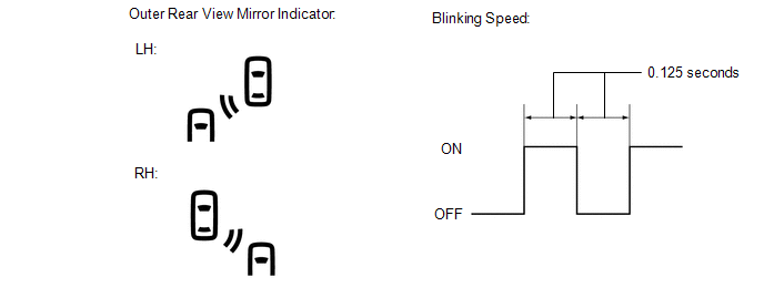
(1) Operation for blind spot monitor function
- When a sensor detects a vehicle in the blind spot area or a vehicle is rapidly approaching the blind spot from behind the vehicle, the outer rear view mirror indicator on the outer rear view mirror assembly illuminates.
- If the turn signal switch is operated, while the sensor is detecting a vehicle in the detection area and the outer rear view mirror indicator on the outer rear view mirror assembly is illuminated, the indicator starts blinking as shown in the illustration.
(2) Operation for RCTA function
- When all of the operation conditions for the RCTA function are met, the outer rear view mirror indicators on the outer rear view mirror assembly blink for 2.5 seconds and the RCTA buzzer (blind spot monitor buzzer) sounds for 2.3 seconds as shown in the illustration.
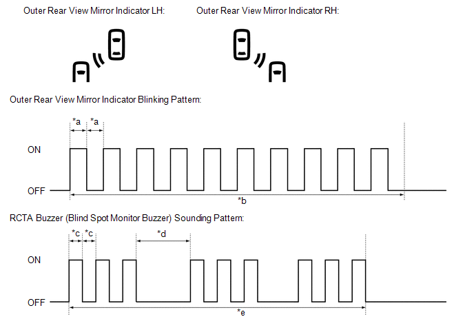
| *a | 0.125 Seconds | *b | 2.5 Seconds |
| *c | 0.1 Seconds | *d | 0.4 Seconds |
| *e | 2.3 Seconds | - | - |
RCTA ICON OUTLINE
(a) If a vehicle approaching from the right or left at the rear of the vehicle is detected, the icon on the detected side will illuminate.
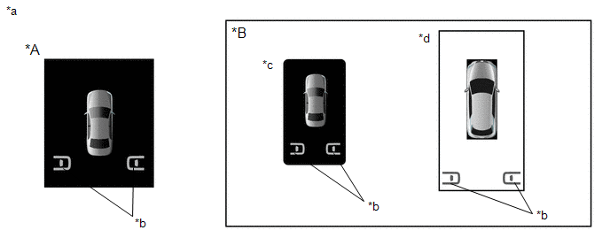
| *A | for 12.3 Inch Display | *B | for 8 Inch Display (w/ Panoramic View Monitor System) |
| *a | Example | *b | RCTA Icon |
| *c | When panoramic view screen not displayed | *d | When panoramic view screen displayed |
 System Diagram
SYSTEM DIAGRAM ...
 How To Proceed With Troubleshooting
CAUTION / NOTICE / HINT HINT:
Use the following procedure to troubleshoot the blind spot monitor system.
*: Use the Techstream.
PROCEDURE 1. VEHICLE BROUGHT TO WORKSHOP
NEXT ...
Other materials:
Lexus RX (RX 350L, RX450h) 2016-2026 Repair Manual > Dynamic Torque Control Awd System: System Description
SYSTEM DESCRIPTION GENERAL DESCRIPTION The dynamic torque control AWD system detects the driving conditions based on signals from each ECU, switches, the steering sensor, the wheel speed sensor, and the acceleration sensor. The system controls the current passing through the 4WD linear solenoid of t ...
Lexus RX (RX 350L, RX450h) 2016-2026 Repair Manual > Accelerator Pedal: Components
COMPONENTS ILLUSTRATION *1 COWL SIDE TRIM BOARD *2 FRONT DOOR SCUFF PLATE LH *3 NO. 1 INSTRUMENT PANEL UNDER COVER SUB-ASSEMBLY - ILLUSTRATION *1 ACCELERATOR PEDAL *2 ACCELERATOR PEDAL PAD *3 ACCELERATOR PEDAL SENSOR ASSEMBLY - - N*m (kgf*cm, ft ...
Lexus RX (RX 350L, RX450h) 2016-{YEAR} Owners Manual
- For your information
- Pictorial index
- For safety and security
- Instrument cluster
- Operation of each component
- Driving
- Lexus Display Audio system
- Interior features
- Maintenance and care
- When trouble arises
- Vehicle specifications
- For owners
Lexus RX (RX 350L, RX450h) 2016-{YEAR} Repair Manual

0.0166