Lexus RX (RX 350L, RX450h) 2016-2026 Repair Manual: VSC OFF Switch Circuit
DESCRIPTION
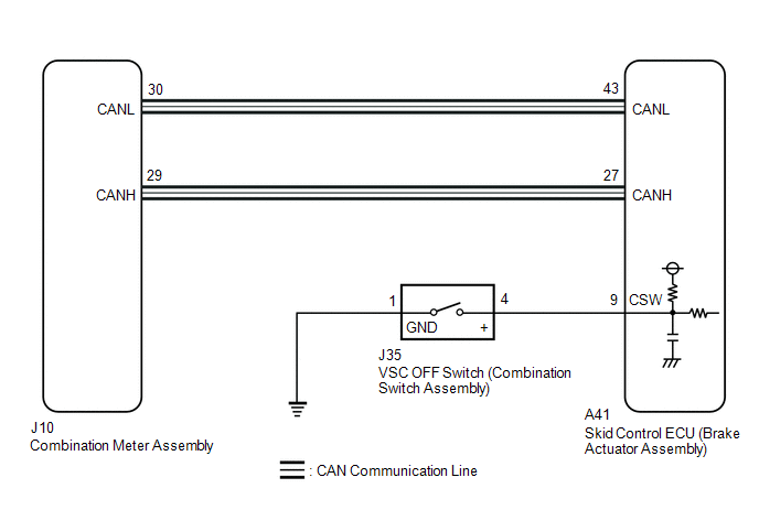
The skid control ECU (brake actuator assembly) is connected to the combination meter assembly via CAN communication.
Pressing the VSC OFF switch (combination switch assembly) turns off TRAC operation, and pressing and holding this switch turns off TRAC and VSC operation. If TRAC and VSC operations are turned off, the TRAC OFF message will be displayed on the multi-information display and the VSC OFF indicator light will come on.
WIRING DIAGRAM
CAUTION / NOTICE / HINT
NOTICE:
After replacing the skid control ECU (brake actuator assembly), perform "Calibration".
Click here .gif)
PROCEDURE
| 1. | READ VALUE USING TECHSTREAM (TRAC/VSC OFF MODE) |
(a) Connect the Techstream to the DLC3.
(b) Turn the engine switch on (IG).
(c) Enter the following menus: Chassis / Brake/EPB / Data List.
Chassis > Brake/EPB > Data List| Tester Display | Measurement Item | Range | Normal Condition | Diagnostic Note |
|---|---|---|---|---|
| TRC(TRAC)/VSC OFF Mode | TRAC/VSC off mode | Normal mode (TRC(TRAC) ON/VSC ON) / TRC(TRAC) OFF mode (TRC(TRAC) OFF/VSC ON) / Not defined / VSC OFF mode (TRC(TRAC) OFF/VSC OFF) | Normal mode (TRC(TRAC) ON/VSC ON): Normal mode TRC(TRAC) OFF mode (TRC(TRAC) OFF/VSC ON): TRAC off mode Not defined: Not defined VSC OFF mode (TRC(TRAC) OFF/VSC OFF): VSC off mode | - |
| Tester Display |
|---|
| TRC(TRAC)/VSC OFF Mode |
(d) Check that the indicator light and mode condition on the Techstream change according to VSC OFF switch (combination switch assembly) operation.
Standard:
| Switch Operation | Mode Condition Display | Multi-information Display (TRAC OFF Message) | VSC OFF Indicator Light |
|---|---|---|---|
| Not pressed | Normal mode (TRC(TRAC) ON/VSC ON) | Not displayed | Does not come on |
| Pressing the VSC OFF switch (combination switch assembly) | TRC(TRAC) OFF mode (TRC(TRAC) OFF/VSC ON) | Displayed | Does not come on |
| Pressing and holding the VSC OFF switch (combination switch assembly) | VSC OFF mode (TRC(TRAC) OFF/VSC OFF) | Displayed | Comes on |
| Result | Proceed to |
|---|---|
| Indicator light and mode condition display do not change. | A |
| Mode condition display is normal, but indicator light does not change. | B |
| Indicator light and mode condition display are normal. | C |
| B | .gif) | INSPECT METER / GAUGE SYSTEM |
| C | | USE SIMULATION METHOD TO CHECK |
|
.gif)
| 2. | INSPECT COMBINATION SWITCH ASSEMBLY |
| (a) Turn the engine switch off. |
|
(b) Make sure that there is no looseness at the locking part and the connecting part of the connectors.
OK:
The connector is securely connected.
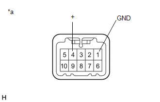
(c) Disconnect the J35 VSC OFF switch (combination switch assembly) connector.
(d) Check both the connector case and the terminals for deformation and corrosion.
OK:
No deformation or corrosion.
(e) Measure the resistance according to the value(s) in the table below.
Standard Resistance:
| Tester Connection | Condition | Specified Condition |
|---|---|---|
| 4 (+) - 1 (GND) | Switch pushed | Below 1 Ω |
| 4 (+) - 1 (GND) | Switch not pushed | 10 kΩ or higher |
| NG | | REPLACE COMBINATION SWITCH ASSEMBLY |
|
| 3. | CHECK HARNESS AND CONNECTOR (BRAKE ACTUATOR ASSEMBLY - COMBINATION SWITCH ASSEMBLY) |
(a) Make sure that there is no looseness at the locking part and the connecting part of the connectors.
OK:
The connector is securely connected.
(b) Disconnect the A41 skid control ECU (brake actuator assembly) connector.
(c) Check both the connector case and the terminals for deformation and corrosion.
OK:
No deformation or corrosion.
(d) Measure the resistance according to the value(s) in the table below.
Standard Resistance:
| Tester Connection | Condition | Specified Condition |
|---|---|---|
| A41-9 (CSW) - J35-4 (+) | Always | Below 1 Ω |
| A41-9 (CSW) or J35-4 (+) - Body ground | Always | 10 kΩ or higher |
| J35-1 (GND) - Body ground | 1 minute or more after disconnecting the cable from the negative (-) battery terminal | Below 1 Ω |
| OK | | REPLACE BRAKE ACTUATOR ASSEMBLY |
| NG | | REPAIR OR REPLACE HARNESS OR CONNECTOR |
 Brake Actuator Operation Sound is Loud during Initial Check
CAUTION / NOTICE / HINT NOTICE: After replacing the skid control ECU (brake actuator assembly), perform "Calibration". Click here PROCEDURE 1. PERFORM ROAD TEST (a) After turning the engine ...
 Vsc Off Switch
...
Other materials:
Lexus RX (RX 350L, RX450h) 2016-2026 Repair Manual > Vehicle Stability Control System: Multi-axis Acceleration Sensor Module "A" Supply Voltage Circuit Voltage Out of Range (C14D71C)
DESCRIPTION for TFT Meter Type:
The airbag sensor assembly has a built-in yaw rate and acceleration sensor and detects the vehicle condition.
This DTC is stored when the skid control ECU (brake actuator assembly) receives a sensor supply voltage malfunction signal from the acceleration sensor (ai ...
Lexus RX (RX 350L, RX450h) 2016-2026 Repair Manual > 2gr-fks (lubrication): Lubrication System
On-vehicle InspectionON-VEHICLE INSPECTION PROCEDURE 1. CHECK ENGINE OIL LEVEL (a) Warm up and stop the engine, then wait for 5 minutes. (b) Check that the engine oil level is between the low level and full level marks on the engine oil level dipstick. If the level is low, check for engine oil leaks ...
Lexus RX (RX 350L, RX450h) 2016-{YEAR} Owners Manual
- For your information
- Pictorial index
- For safety and security
- Instrument cluster
- Operation of each component
- Driving
- Lexus Display Audio system
- Interior features
- Maintenance and care
- When trouble arises
- Vehicle specifications
- For owners
Lexus RX (RX 350L, RX450h) 2016-{YEAR} Repair Manual

0.0107