Lexus RX (RX 350L, RX450h) 2016-2026 Repair Manual: Installation
INSTALLATION
PROCEDURE
1. INSTALL BRAKE BOOSTER GASKET
(a) Install a new brake booster gasket to the brake booster assembly.
2. INSTALL BRAKE BOOSTER ASSEMBLY
(a) Temporarily install the brake booster assembly to the vehicle body.
NOTICE:
Do not apply excessive force to the brake lines.
(b) Temporarily install the lock nut and brake master cylinder push rod clevis to the brake booster assembly.
NOTICE:
Fully tighten the lock nut when adjusting the brake pedal height.
(c) Install the 4 nuts to secure the brake booster assembly.
Torque:
14 N·m {143 kgf·cm, 10 ft·lbf}
3. INSTALL PUSH ROD PIN
Click here .gif)
4. INSTALL BRAKE PEDAL RETURN SPRING
Click here
5. INSTALL BRAKE LINE
(a) Install the 2 brake lines to the brake tube clamp.
NOTICE:
- Do not kink or damage the brake lines.
- Do not damage the clamp.
6. INSTALL AIR CONDITIONING HOSE AND ACCESSORY (w/ Rear Air Conditioning System)
(a) Install the air conditioner tube and accessory assembly with the nut.
Torque:
9.8 N·m {100 kgf·cm, 87 in·lbf}
NOTICE:
- Do not deform the refrigerant lines.
- Do not damage the clamp.
7. CONNECT FUEL VAPOR FEED HOSE ASSEMBLY
(a) Connect the fuel vapor feed hose assembly, and slide the clip to secure it.
8. INSTALL ENGINE ROOM MAIN WIRE (for TMC Made)
(a) Install the engine room relay block assembly with the 3 bolts.
Torque:
8.35 N·m {85 kgf·cm, 74 in·lbf}
(b) Engage the clamp.
| (c) Engage the clamp and pin to install the wire harness protector. |
|
.png)
(d) Install the bolt to secure the wire harness protector.
Torque:
8.35 N·m {85 kgf·cm, 74 in·lbf}
(e) Connect the connector to the security horn assembly.
(f) Connect the connector to the vacuum warning switch assembly.
(g) Engage the 6 clamps to install the engine room main wire.
9. INSTALL ENGINE ROOM MAIN WIRE (for TMMC Made)
(a) Install the engine room relay block assembly with the 3 bolts.
Torque:
8.35 N·m {85 kgf·cm, 74 in·lbf}
(b) Engage the clamp.
| (c) Engage the clamp and pin to install the wire harness protector. |
|
.png)
(d) Install the bolt to secure the wire harness protector.
Torque:
8.35 N·m {85 kgf·cm, 74 in·lbf}
(e) w/ Security Horn Assembly:
(1) Connect the connector to the security horn assembly.
(f) Connect the connector to the vacuum warning switch assembly.
(g) Engage the 6 clamps to install the engine room main wire.
10. CONNECT UNION TO CHECK VALVE HOSE
(a) w/o Rear Air Conditioning System:
| (1) Connect the union to check valve hose to the brake booster assembly, and slide the clip to secure it. |
|
.png)
(2) Install the union to check valve hose to the engine room main wire.
(b) w/ Rear Air Conditioning System:
| (1) Connect the union to check valve hose to the brake booster assembly, and slide the clip to secure it. |
|
.png)
(2) Engage the clamp to install the union to check valve hose to the suction pipe sub-assembly.
11. INSTALL RESERVOIR BRACKET
(a) Install the reservoir bracket with the 2 bolts.
Torque:
9.0 N·m {92 kgf·cm, 80 in·lbf}
12. INSTALL BRAKE MASTER CYLINDER RESERVOIR ASSEMBLY
| (a) Move the brake master cylinder reservoir assembly as shown in the illustration to engage the 2 claws. |
|
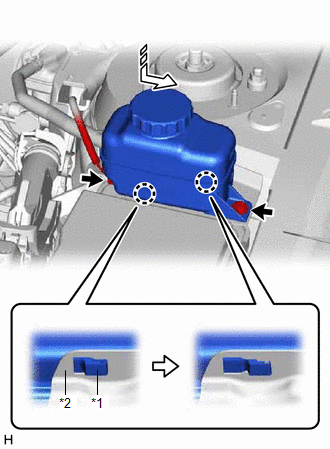
(b) Connect the reservoir level switch connector and install the bolt.
Torque:
9.0 N·m {92 kgf·cm, 80 in·lbf}
13. INSTALL OUTER COWL TOP PANEL SUB-ASSEMBLY
Click here
14. INSTALL FRONT WIPER MOTOR AND LINK ASSEMBLY
Click here
15. INSTALL NO. 1 INSTRUMENT PANEL UNDER COVER SUB-ASSEMBLY
Click here
16. INSTALL COWL SIDE TRIM BOARD LH
Click here
17. INSTALL FRONT DOOR SCUFF PLATE LH
w/o Rear No. 2 Seat: Click here
w/ Rear No. 2 Seat: Click here
18. INSTALL BRAKE MASTER CYLINDER SUB-ASSEMBLY WITH WAY
Click here
19. CONNECT CABLE TO NEGATIVE BATTERY TERMINAL
NOTICE:
When disconnecting the cable, some systems need to be initialized after the cable is reconnected.
Click here
20. INSPECT AND ADJUST BRAKE PEDAL
Click here
 Reassembly
REASSEMBLY PROCEDURE 1. INSTALL VACUUM WARNING SWITCH ASSEMBLY (for TMC Made) (a) Install a new check valve grommet to the brake booster assembly. (b) Install the vacuum warning switch assembly to the ...
 Brake Fluid
...
Other materials:
Lexus RX (RX 350L, RX450h) 2016-2026 Repair Manual > Power Tilt And Power Telescopic Steering Column System: Freeze Frame Data
FREEZE FRAME DATA FREEZE FRAME DATA NOTICE:
Freeze frame data values will vary depending on the measurement conditions, surroundings, or vehicle conditions. For this reason, there may be a problem even when the values are within specifications.
Turn the engine switch on (IG) and park the vehicl ...
Lexus RX (RX 350L, RX450h) 2016-2026 Repair Manual > Smart Access System With Push-button Start (for Entry Function): Open in Outside Luggage Compartment Electrical Key Antenna Circuit (B27A8)
DESCRIPTION The certification ECU (smart key ECU assembly) generates a request signal and transmits the signal to the electrical key antenna (outside luggage compartment). For the electrical key antenna (outside luggage compartment) to detect when the electrical key transmitter sub-assembly is broug ...
Lexus RX (RX 350L, RX450h) 2016-{YEAR} Owners Manual
- For your information
- Pictorial index
- For safety and security
- Instrument cluster
- Operation of each component
- Driving
- Lexus Display Audio system
- Interior features
- Maintenance and care
- When trouble arises
- Vehicle specifications
- For owners
Lexus RX (RX 350L, RX450h) 2016-{YEAR} Repair Manual

0.0125