Lexus RX (RX 350L, RX450h) 2016-2026 Repair Manual: Removal
REMOVAL
CAUTION / NOTICE / HINT
The necessary procedures (adjustment, calibration, initialization, or registration) that must be performed after parts are removed, installed, or replaced during vacuum pump assembly removal/installation are shown below.
Necessary Procedure After Parts Removed/Installed/Replaced| Replacement Part or Procedure | Necessary Procedures | Effects/Inoperative when not Performed | Link |
|---|---|---|---|
| Disconnect cable from negative battery terminal | Memorize steering angle neutral point | Lane control system | |
| Pre-collision system | |||
| Intelligent clearance sonar system | |||
| Lighting system (w/ Automatic Headlight Beam Level Control System) | | ||
| Parking assist monitor system | | ||
| Panoramic view monitor system | | ||
| Initialize back door lock | Power door lock control system | | |
| Reset back door close position | Power back door system (w/ Outside Door Control Switch) | |
PROCEDURE
1. PRECAUTION
NOTICE:
After turning the engine switch off, waiting time may be required before disconnecting the cable from the negative (-) battery terminal. Therefore, make sure to read the disconnecting the cable from the negative (-) battery terminal notices before proceeding with work.
Click here .gif)
2. DISCONNECT CABLE FROM NEGATIVE BATTERY TERMINAL
NOTICE:
When disconnecting the cable, some systems need to be initialized after the cable is reconnected.
Click here
3. REMOVE THROTTLE BODY WITH MOTOR ASSEMBLY
Click here
4. REMOVE FRONT WHEEL LH
Click here
5. REMOVE COOL AIR INTAKE DUCT SEAL
Click here
6. REMOVE V-BANK COVER SUB-ASSEMBLY
Click here
7. REMOVE INLET AIR CLEANER ASSEMBLY
Click here
8. REMOVE AIR CLEANER FILTER ELEMENT SUB-ASSEMBLY
Click here
9. REMOVE AIR CLEANER CASE SUB-ASSEMBLY
Click here
10. REMOVE AIR CLEANER BRACKET
Click here
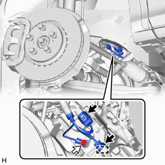
11. SEPARATE TRANSMISSION CONTROL CABLE ASSEMBLY
| (a) Remove the nut and separate the transmission control cable assembly from the transmission control shaft lever. |
|
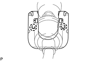
(b) Using a screwdriver, disengage the 4 claws and disconnect the transmission control cable assembly with clip from the No. 1 transmission control cable bracket.
| (c) Using a screwdriver, disengage the 2 claws and remove the clip from the transmission control cable assembly. |
|
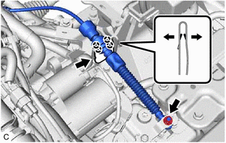
12. DISCONNECT AIR TUBE
| (a) Slide the clip and disconnect the air tube from the vacuum pump assembly. |
|
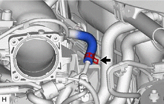
13. DISCONNECT VENTILATION HOSE
| (a) Slide the clip and disconnect the ventilation hose. |
|
14. DISCONNECT HEATER WATER HOSE
| (a) Disengage the clamp. |
|
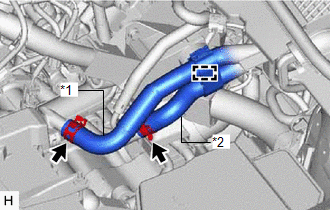
(b) Slide the 2 clips and disconnect the inlet heater water hose and outlet heater water hose.
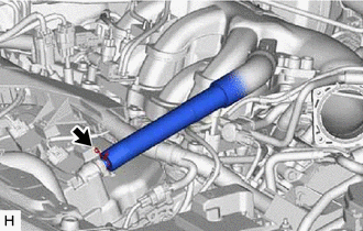
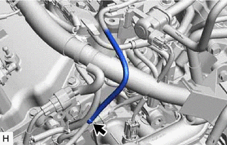
15. DISCONNECT VACUUM HOSE SUB-ASSEMBLY
| (a) Disconnect the vacuum hose sub-assembly. |
|
16. REMOVE NO. 2 ENGINE UNDER COVER
Click here
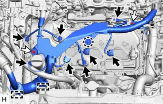
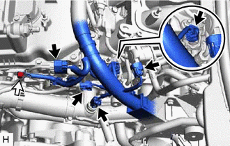
17. SEPARATE ENGINE WIRE
(a) Disconnect the 2 connectors.
.png) | Connector |
.png) | Bolt |
(b) Disengage the clamp.
(c) Remove the bolt.
(d) Disconnect the 8 connectors.
| | Connector |
| | Bolt |
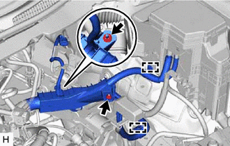
(e) Disengage the 2 clamps and claw.
(f) Remove the 2 bolts.
(g) Disconnect the 5 connectors.
| | Connector |
| | Bolt |
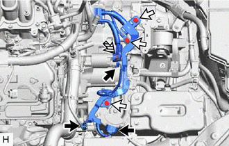
(h) Remove the bolt.
| (i) Disengage the 2 clamps. |
|
(j) Remove the 2 nuts.
(k) Disconnect the 3 connectors.
| | Connector |
| | Bolt |
 | Nut |
(l) Remove the 3 bolts and nut.
(m) Remove the bolt and nut to separate the engine wire.
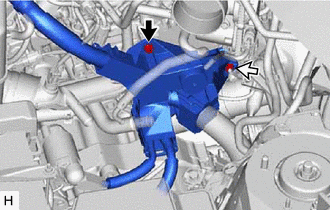
| | Bolt |
| | Nut |
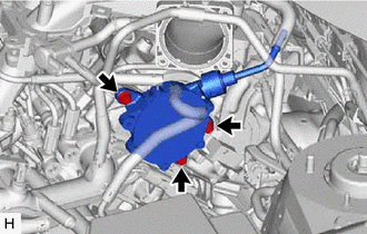
18. REMOVE VACUUM PUMP ASSEMBLY
| (a) Remove the 3 bolts and vacuum pump assembly from the engine assembly. |
|
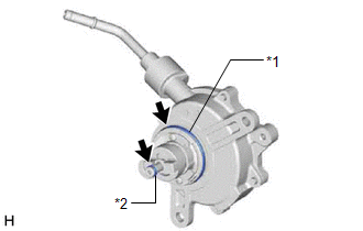
| (b) Remove the No. 2 O-ring and No. 3 O-ring from the vacuum pump assembly. |
|
 Reassembly
REASSEMBLY PROCEDURE 1. INSTALL VACUUM PUMP VANE (for TMC Made) (a) Apply engine oil to the vacuum pump vane and vacuum pump vane caps and install the vacuum pump vane caps to the vacuum pump vane. (b ...
 Installation
INSTALLATION PROCEDURE 1. INSTALL VACUUM PUMP ASSEMBLY (a) When using a new vacuum pump assembly: (1) Apply engine oil to the No. 2 O-ring and No. 3 O-ring which are installed to a new vacuum pump ass ...
Other materials:
Lexus RX (RX 350L, RX450h) 2016-2026 Repair Manual > Throttle Body: Inspection
INSPECTION PROCEDURE 1. INSPECT THROTTLE BODY WITH MOTOR ASSEMBLY (a) Measure the resistance according to the value(s) in the table below. Standard Resistance: Tester Connection Condition Specified Condition 1 (M-) - 2 (M+) 20°C (68°F) 0.3 to 100 Ω If the result is not as sp ...
Lexus RX (RX 350L, RX450h) 2016-2026 Repair Manual > Intake System: System Diagram
SYSTEM DIAGRAM *1 Throttle Body with Motor Assembly *2 Intake Air Control Valve (for ACIS) *3 Intake Air Control Valve Actuator (for ACIS) *4 ECM *5 Vacuum Switching Valve (for ACIS) - - *a Engine Speed Signal *b from Vacuum Tank ...
Lexus RX (RX 350L, RX450h) 2016-{YEAR} Owners Manual
- For your information
- Pictorial index
- For safety and security
- Instrument cluster
- Operation of each component
- Driving
- Lexus Display Audio system
- Interior features
- Maintenance and care
- When trouble arises
- Vehicle specifications
- For owners
Lexus RX (RX 350L, RX450h) 2016-{YEAR} Repair Manual

0.0097