Lexus RX (RX 350L, RX450h) 2016-2026 Repair Manual: Installation
INSTALLATION
PROCEDURE
1. INSTALL VACUUM PUMP ASSEMBLY
(a) When using a new vacuum pump assembly:
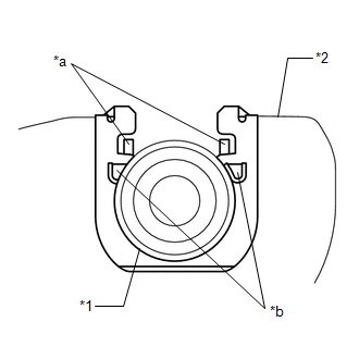
(1) Apply engine oil to the No. 2 O-ring and No. 3 O-ring which are installed to a new vacuum pump assembly.
.png)
| *1 | No. 2 O-ring |
| *2 | No. 3 O-ring |
.png) | Engine oil |
(b) When reusing the vacuum pump assembly:
(1) Apply engine oil to a new No. 2 O-ring and No. 3 O-ring and install them to the vacuum pump assembly.
| *1 | No. 2 O-ring |
| *2 | No. 3 O-ring |
| | Engine oil |
(c) Apply engine oil to the inner surface of the installation hole.
| (d) Install the vacuum pump assembly so that the oil pipe engages with the hole of the camshaft and the coupling teeth with the grooves on the camshaft tip. NOTICE:
|
|
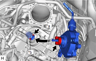
| (e) Install the vacuum pump assembly with the 3 bolts. Torque: 21 N·m {214 kgf·cm, 15 ft·lbf} NOTICE: After installation, check that there are no gaps between the matching surfaces and that the vacuum pump assembly is not installed at an angle. |
|
.png)
2. INSTALL ENGINE WIRE
(a) Install the engine wire with the bolt and nut.
.png)
| | Bolt |
.png) | Nut |
Torque:
8.35 N·m {85 kgf·cm, 74 in·lbf}
(b) Install the 3 bolts and nut.
.png)
| | Connector |
| | Bolt |
.png) | Nut |
Torque:
Bolt :
19.1 N·m {195 kgf·cm, 14 ft·lbf}
Nut :
9.8 N·m {100 kgf·cm, 87 in·lbf}
(c) Connect the 3 connectors.
| (d) Install the 2 nuts. Torque: 8.35 N·m {85 kgf·cm, 74 in·lbf} |
|
.png)
(e) Engage the 2 clamps.
(f) Install the bolt.
.png)
| | Connector |
| | Bolt |
Torque:
8.35 N·m {85 kgf·cm, 74 in·lbf}
(g) Connect the 5 connectors.
(h) Install the 2 bolts.
.png)
| | Connector |
| | Bolt |
Torque:
8.35 N·m {85 kgf·cm, 74 in·lbf}
(i) Engage the 2 clamps and claw.
(j) Connect the 8 connectors.
(k) Install the bolt.
.png)
| | Connector |
| | Bolt |
Torque:
8.35 N·m {85 kgf·cm, 74 in·lbf}
(l) Engage the clamp.
(m) Connect the 2 connectors.
3. INSTALL NO. 2 ENGINE UNDER COVER
Click here .gif)
4. CONNECT VACUUM HOSE SUB-ASSEMBLY
(a) Connect the vacuum hose sub-assembly.
5. CONNECT HEATER WATER HOSE
| (a) Connect the inlet heater water hose and outlet heater water hose, and slide the 2 clips to secure them. |
|
.png)
(b) Engage the clamp.
6. CONNECT VENTILATION HOSE
(a) Connect the ventilation hose, and slide the clip to secure it.
7. CONNECT AIR TUBE
(a) Connect the air tube to the vacuum pump assembly, and slide the clip to secure it.
8. INSTALL TRANSMISSION CONTROL CABLE ASSEMBLY
(a) Install a new clip to the No. 1 transmission control cable bracket.
| (b) Connect the transmission control cable assembly to the No. 1 transmission control cable bracket. NOTICE:
|
|
(c) Connect the transmission control cable assembly to the transmission control shaft lever with the nut.
Torque:
12 N·m {122 kgf·cm, 9 ft·lbf}
9. INSTALL AIR CLEANER BRACKET
Click here
10. INSTALL AIR CLEANER CASE SUB-ASSEMBLY
Click here
11. INSTALL AIR CLEANER FILTER ELEMENT SUB-ASSEMBLY
Click here
12. INSTALL INLET AIR CLEANER ASSEMBLY
Click here
13. INSTALL V-BANK COVER SUB-ASSEMBLY
Click here
14. INSTALL COOL AIR INTAKE DUCT SEAL
Click here
15. INSTALL FRONT WHEEL LH
Click here
16. CONNECT CABLE TO NEGATIVE BATTERY TERMINAL
NOTICE:
When disconnecting the cable, some systems need to be initialized after the cable is reconnected.
Click here
17. INSTALL THROTTLE BODY WITH MOTOR ASSEMBLY
Click here
18. INSPECT VACUUM PUMP OPERATION
Click here
 Removal
REMOVAL CAUTION / NOTICE / HINT The necessary procedures (adjustment, calibration, initialization, or registration) that must be performed after parts are removed, installed, or replaced during vacuum ...

Other materials:
Lexus RX (RX 350L, RX450h) 2016-2026 Repair Manual > Hood: Adjustment
ADJUSTMENT CAUTION / NOTICE / HINT *a Centering Bolt *b Standard Bolt HINT:
Centering bolts are used to install the hood hinges and hood lock. The hood and hood lock cannot be adjusted with the centering bolts installed. Substitute the centering bolts with standard bolts (with wash ...
Lexus RX (RX 350L, RX450h) 2016-2026 Repair Manual > Rear Door Speaker: Inspection
INSPECTION PROCEDURE 1. INSPECT REAR SPEAKER ASSEMBLY (a) With the speaker installed, check that there is no looseness or other abnormalities. (b) Check that there is no foreign matter in the speaker, no tears on the speaker cone or other abnormalities. (c) Measure the resistance of the speaker. ...
Lexus RX (RX 350L, RX450h) 2016-{YEAR} Owners Manual
- For your information
- Pictorial index
- For safety and security
- Instrument cluster
- Operation of each component
- Driving
- Lexus Display Audio system
- Interior features
- Maintenance and care
- When trouble arises
- Vehicle specifications
- For owners
Lexus RX (RX 350L, RX450h) 2016-{YEAR} Repair Manual

0.0149