Lexus RX (RX 350L, RX450h) 2016-2026 Repair Manual: Left Electric Parking Brake Actuator Circuit Current Above Threshold (C060E19)
DESCRIPTION
| DTC No. | Detection Item | DTC Detection Condition | Trouble Area | Memory | Note |
|---|---|---|---|---|---|
| C060E19 | Left Electric Parking Brake Actuator Circuit Current Above Threshold | When the electric parking brake is operating, overcurrent is detected in the parking brake actuator assembly LH 3 times |
| DTC stored | An electric parking brake system malfunction is displayed on the multi-information display. |
WIRING DIAGRAM
Click here .gif)
CAUTION / NOTICE / HINT
NOTICE:
- The electric parking brake may still operate up to 20 seconds after the engine switch is turned off. Before disconnecting connectors or fuses, turn the engine switch off and wait 20 seconds or more.
-
After replacing the skid control ECU (brake actuator assembly), perform "Calibration".
Click here
- When replacing the skid control ECU (brake actuator assembly), operate the electric parking brake switch (electric parking brake switch assembly) as the parking brake indicator light blinks (red) when the engine switch is first turned on (IG).
PROCEDURE
| 1. | INSPECT NO. 2 PARKING BRAKE WIRE ASSEMBLY |
(a) Make sure that there is no looseness at the locking part and the connecting part of the connectors.
OK:
The connector is securely connected.
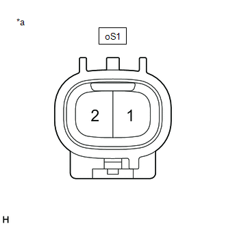
(b) Disconnect the oS1 and o2 No. 2 parking brake wire assembly connectors.
(c) Check both the connector case and the terminals for deformation and corrosion.
OK:
No deformation or corrosion.
(d) Measure the resistance according to the value(s) in the table below.
.png)
| *a | Front view of No. 2 Parking Brake Wire Assembly | *b | (to wire harness connector) |
| *c | (to Parking Brake Actuator Assembly LH) | - | - |
Standard Resistance:
| Tester Connection | Condition | Specified Condition |
|---|---|---|
| oS1-1 - o2-2 (MRL+) | Always | Below 1 Ω |
| oS1-1 or o2-2 (MRL+) - Body ground and other terminals | Always | 10 kΩ or higher |
| oS1-2 - o2-1 (MRL-) | Always | Below 1 Ω |
| oS1-2 or o2-1 (MRL-) - Body ground and other terminals | Always | 10 kΩ or higher |
| NG | .gif) | REPLACE NO. 2 PARKING BRAKE WIRE ASSEMBLY |
|
.gif)
| 2. | CHECK HARNESS AND CONNECTOR (SKID CONTROL ECU (BRAKE ACTUATOR ASSEMBLY) - PARKING BRAKE ACTUATOR ASSEMBLY LH) |
(a) Make sure the No. 2 parking brake wire assembly is securely installed.
(b) Disconnect the A41 skid control ECU (brake actuator assembly) connector.
(c) Disconnect the o2 parking brake actuator assembly LH connector.
(d) Measure the resistance according to the value(s) in the table below.
Standard Resistance:
| Tester Connection | Condition | Specified Condition |
|---|---|---|
| A41-3 (MRL+) - o2-2 (MRL+) | Always | Below 1 Ω |
| A41-3 (MRL+) or o2-2 (MRL+) - Body ground | Always | 10 kΩ or higher |
| A41-2 (MRL-) - o2-1 (MRL-) | Always | Below 1 Ω |
| A41-2 (MRL-) or o2-1 (MRL-) - Body ground | Always | 10 kΩ or higher |
| NG | | REPAIR OR REPLACE HARNESS OR CONNECTOR |
|
| 3. | INSPECT PARKING BRAKE ACTUATOR ASSEMBLY LH |
(a) Remove the parking brake actuator assembly LH.
Click here
(b) Inspect the parking brake actuator assembly LH.
Click here
| NG | | REPLACE PARKING BRAKE ACTUATOR ASSEMBLY LH |
|
| 4. | CHECK FOR SHORT TO +B |
(a) Make sure the No. 2 parking brake wire assembly is securely installed.
(b) Disconnect the o2 parking brake actuator assembly LH connector.
| (c) Measure the voltage according to the value(s) in the table below. Standard Voltage:
|
|
.png)
| OK | | REPLACE PARKING BRAKE ACTUATOR ASSEMBLY LH |
|
| 5. | CHECK FOR SHORT TO +B |
(a) Disconnect the oS1 No. 2 parking brake wire assembly connector.
| (b) Measure the voltage according to the value(s) in the table below. Standard Voltage:
|
|
| OK | | REPLACE NO. 2 PARKING BRAKE WIRE ASSEMBLY |
|
| 6. | CHECK FOR SHORT TO +B |
(a) Disconnect the oS1 No. 2 parking brake wire assembly connector.
(b) Disconnect the A41 skid control ECU (brake actuator assembly) connector.
(c) Measure the voltage according to the value(s) in the table below.
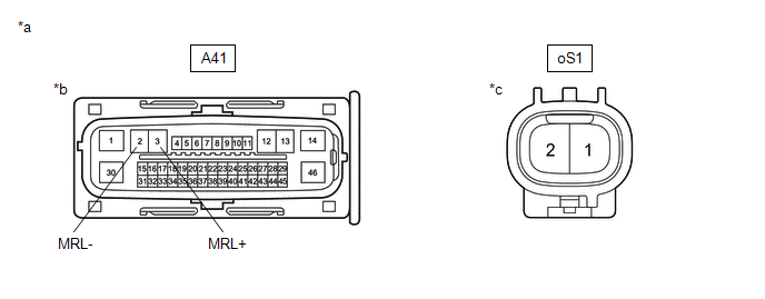
| *a | Front view of wire harness connector | *b | (to Skid Control ECU (Brake Actuator Assembly)) |
| *c | (to No. 2 Parking Brake Wire Assembly) | - | - |
Standard Voltage:
| Tester Connection | Condition | Specified Condition |
|---|---|---|
| oS1-1 or A41-3 (MRL+) - Body ground | Always | Below 1 V |
| oS1-2 or A41-2 (MRL-) - Body ground | Always | Below 1 V |
| OK | | REPLACE SKID CONTROL ECU (BRAKE ACTUATOR ASSEMBLY) |
| NG | | REPAIR OR REPLACE HARNESS OR CONNECTOR |
 Left Electric Parking Brake Actuator Control Circuit Short to Ground or Open (C060B14)
DESCRIPTION DTC No. Detection Item DTC Detection Condition Trouble Area Memory Note C060B14 Left Electric Parking Brake Actuator Control Circuit Short to Ground or Open
Diagnos ...
 Left Electric Parking Brake Actuator Signal Stuck In Range (C060E2A)
DESCRIPTION DTC No. Detection Item DTC Detection Condition Trouble Area Memory Note C060E2A Left Electric Parking Brake Actuator Signal Stuck In Range
Diagnosis Condition:
Elec ...
Other materials:
Lexus RX (RX 350L, RX450h) 2016-2026 Repair Manual > Airbag System: Short in D Squib Circuit (B1800-B1803)
DESCRIPTION The driver squib circuit consists of the airbag sensor assembly, spiral cable sub-assembly and horn button assembly. The airbag sensor assembly uses this circuit to deploy the airbag when deployment conditions are met. These DTCs are stored when a malfunction is detected in the driver sq ...
Lexus RX (RX 350L, RX450h) 2016-2026 Repair Manual > Audio And Visual System (for 8 Inch Display): Voice is not Recognized
PROCEDURE 1. CHECK CONDITION (a) While paying attention to the condition of the spoken voice command, perform a voice recognition operation. OK: Voice command is recognized normally. HINT:
When the voice command is recognized, the content of the voice command is displayed in the voice r ...
Lexus RX (RX 350L, RX450h) 2016-{YEAR} Owners Manual
- For your information
- Pictorial index
- For safety and security
- Instrument cluster
- Operation of each component
- Driving
- Lexus Display Audio system
- Interior features
- Maintenance and care
- When trouble arises
- Vehicle specifications
- For owners
Lexus RX (RX 350L, RX450h) 2016-{YEAR} Repair Manual

0.0119