Lexus RX (RX 350L, RX450h) 2016-2026 Repair Manual: Right Electric Parking Brake Actuator Circuit Current Above Threshold (C061319)
DESCRIPTION
| DTC No. | Detection Item | DTC Detection Condition | Trouble Area | Memory | Note |
|---|---|---|---|---|---|
| C061319 | Right Electric Parking Brake Actuator Circuit Current Above Threshold | When the electric parking brake is operating, overcurrent is detected in the parking brake actuator assembly RH 3 times |
| DTC stored | An electric parking brake system malfunction is displayed on the multi-information display. |
WIRING DIAGRAM
Click here .gif)
CAUTION / NOTICE / HINT
NOTICE:
- The electric parking brake may still operate up to 20 seconds after the engine switch is turned off. Before disconnecting connectors or fuses, turn the engine switch off and wait 20 seconds or more.
-
After replacing the skid control ECU (brake actuator assembly), perform "Calibration".
Click here
- When replacing the skid control ECU (brake actuator assembly), operate the electric parking brake switch (electric parking brake switch assembly) as the parking brake indicator light blinks (red) when the engine switch is first turned on (IG).
PROCEDURE
| 1. | INSPECT NO. 1 PARKING BRAKE WIRE ASSEMBLY |
(a) Make sure that there is no looseness at the locking part and the connecting part of the connectors.
OK:
The connector is securely connected.
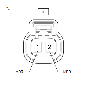
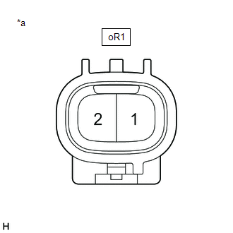
(b) Disconnect the oR1 and o1 No. 1 parking brake wire assembly connectors.
(c) Check both the connector case and the terminals for deformation and corrosion.
OK:
No deformation or corrosion.
(d) Measure the resistance according to the value(s) in the table below.
.png)
| *a | Front view of No. 1 Parking Brake Wire Assembly | *b | (to wire harness connector) |
| *c | (to Parking Brake Actuator Assembly RH) | - | - |
Standard Resistance:
| Tester Connection | Condition | Specified Condition |
|---|---|---|
| oR1-1 - o1-2 (MRR+) | Always | Below 1 Ω |
| oR1-1 or o1-2 (MRR+) - Body ground and other terminals | Always | 10 kΩ or higher |
| oR1-2 - o1-1 (MRR-) | Always | Below 1 Ω |
| oR1-2 or o1-1 (MRR-) - Body ground and other terminals | Always | 10 kΩ or higher |
| NG | .gif) | REPLACE NO. 1 PARKING BRAKE WIRE ASSEMBLY |
|
.gif)
| 2. | CHECK HARNESS AND CONNECTOR (SKID CONTROL ECU (BRAKE ACTUATOR ASSEMBLY) - PARKING BRAKE ACTUATOR ASSEMBLY RH) |
(a) Make sure the No. 1 parking brake wire assembly is securely installed.
(b) Disconnect the A41 skid control ECU (brake actuator assembly) connector.
(c) Disconnect the o1 parking brake actuator assembly RH connector.
(d) Measure the resistance according to the value(s) in the table below.
Standard Resistance:
| Tester Connection | Condition | Specified Condition |
|---|---|---|
| A41-13 (MRR+) - o1-2 (MRR+) | Always | Below 1 Ω |
| A41-13 (MRR+) or o1-2 (MRR+) - Body ground | Always | 10 kΩ or higher |
| A41-12 (MRR-) - o1-1 (MRR-) | Always | Below 1 Ω |
| A41-12 (MRR-) or o1-1 (MRR-) - Body ground | Always | 10 kΩ or higher |
| NG | | REPAIR OR REPLACE HARNESS OR CONNECTOR |
|
| 3. | INSPECT PARKING BRAKE ACTUATOR ASSEMBLY RH |
(a) Remove the parking brake actuator assembly RH.
Click here
(b) Inspect the parking brake actuator assembly RH.
Click here
| NG | | REPLACE PARKING BRAKE ACTUATOR ASSEMBLY RH |
|
| 4. | CHECK FOR SHORT TO +B |
(a) Turn the engine switch off.
(b) Make sure the No. 1 parking brake wire assembly is securely installed.
(c) Disconnect the o1 parking brake actuator assembly RH connector.
| (d) Measure the voltage according to the value(s) in the table below. Standard Voltage:
|
|
| OK | | REPLACE PARKING BRAKE ACTUATOR ASSEMBLY RH |
|
| 5. | CHECK FOR SHORT TO +B |
(a) Disconnect the oR1 No. 1 parking brake wire assembly connector.
| (b) Measure the voltage according to the value(s) in the table below. Standard Voltage:
|
|
| OK | | REPLACE NO. 1 PARKING BRAKE WIRE ASSEMBLY |
|
| 6. | CHECK FOR SHORT TO +B |
(a) Disconnect the oR1 No. 1 parking brake wire assembly connector.
(b) Disconnect the A41 skid control ECU (brake actuator assembly) connector.
(c) Measure the voltage according to the value(s) in the table below.
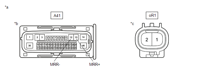
| *a | Front view of wire harness connector | *b | (to Skid Control ECU (Brake Actuator Assembly)) |
| *c | (to No. 1 Parking Brake Wire Assembly) | - | - |
Standard Voltage:
| Tester Connection | Condition | Specified Condition |
|---|---|---|
| oR1-1 or A41-13 (MRR+) - Body ground | Always | Below 1 V |
| oR1-2 or A41-12 (MRR-) - Body ground | Always | Below 1 V |
| OK | | REPLACE SKID CONTROL ECU (BRAKE ACTUATOR ASSEMBLY) |
| NG | | REPAIR OR REPLACE HARNESS OR CONNECTOR |
 Right Electric Parking Brake Actuator Control Circuit Short to Ground or Open (C061014)
DESCRIPTION DTC No. Detection Item DTC Detection Condition Trouble Area Memory Note C061014 Right Electric Parking Brake Actuator Control Circuit Short to Ground or Open
Diagno ...
 Right Electric Parking Brake Actuator Signal Stuck In Range (C06132A)
DESCRIPTION DTC No. Detection Item DTC Detection Condition Trouble Area Memory Note C06132A Right Electric Parking Brake Actuator Signal Stuck In Range
Diagnosis Condition:
Ele ...
Other materials:
Lexus RX (RX 350L, RX450h) 2016-2026 Repair Manual > Can Communication System: Lost Communication with Gateway Module (Main Body ECU) (U1002)
DESCRIPTION
The main body ECU (multiplex network body ECU) will store this DTC when no signals can be received from the ECUs that have been memorized as those that are connected to sub bus 1.
When the main body ECU (multiplex network body ECU) receives a response signal from the ECUs connected ...
Lexus RX (RX 350L, RX450h) 2016-2026 Repair Manual > Generator (for 150 A Type): Reassembly
REASSEMBLY PROCEDURE 1. INSTALL GENERATOR DRIVE END FRAME BEARING (a) Using SST and a press, install a new generator drive end frame bearing. SST: 09950-60010 09951-00470 SST: 09950-70010 09951-07100 (b) Fit the tabs of the retainer plate into the cutouts of the generator drive end ...
Lexus RX (RX 350L, RX450h) 2016-{YEAR} Owners Manual
- For your information
- Pictorial index
- For safety and security
- Instrument cluster
- Operation of each component
- Driving
- Lexus Display Audio system
- Interior features
- Maintenance and care
- When trouble arises
- Vehicle specifications
- For owners
Lexus RX (RX 350L, RX450h) 2016-{YEAR} Repair Manual

0.0092