Lexus RX (RX 350L, RX450h) 2016-2026 Repair Manual: Steering Knuckle
Components
COMPONENTS
ILLUSTRATION

| *A | Nut Type A | *B | Nut Type B |
| *1 | FRONT LOWER BALL JOINT ASSEMBLY | *2 | STEERING KNUCKLE |
| *3 | FRONT AXLE HUB SUB-ASSEMBLY | *4 | FRONT DISC BRAKE DUST COVER |
| *5 | COTTER PIN | - | - |
.png) | N*m (kgf*cm, ft.*lbf): Specified torque | ● | Non-reusable part |
Installation
INSTALLATION
CAUTION / NOTICE / HINT
HINT:
- Use the same procedure for the RH side and LH side.
- The following procedure is for the LH side.
PROCEDURE
1. INSTALL STEERING KNUCKLE
(a) Secure the steering knuckle between aluminum plates in a vise.
NOTICE:
Do not overtighten the vise.
(b) Install the front axle hub sub-assembly and front disc brake dust cover to the steering knuckle with the 4 bolts.
Torque:
96 N·m {979 kgf·cm, 71 ft·lbf}
NOTICE:
- Be careful not to damage the speed sensor rotor or contact surfaces.
- Do not allow foreign matter to contact the speed sensor rotor or contact surfaces.
2. INSTALL FRONT LOWER BALL JOINT ASSEMBLY
Click here .gif)
3. INSTALL FRONT AXLE ASSEMBLY
Click here .gif)
Removal
REMOVAL
CAUTION / NOTICE / HINT
The necessary procedures (adjustment, calibration, initialization, or registration) that must be performed after parts are removed and installed, or replaced during steering knuckle removal/installation are shown below.
Necessary Procedures After Parts Removed/Installed/Replaced| Replaced Part or Performed Procedure | Necessary Procedure | Effect/Inoperative Function when Necessary Procedure not Performed | Link |
|---|---|---|---|
| Front wheel alignment adjustment | Calibration |
| |
HINT:
- Use the same procedure for the RH side and LH side.
- The following procedure is for the LH side.
PROCEDURE
1. REMOVE FRONT AXLE ASSEMBLY
Click here .gif)
2. REMOVE FRONT LOWER BALL JOINT ASSEMBLY
Click here .gif)
3. REMOVE STEERING KNUCKLE
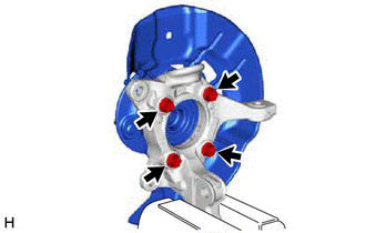
| (a) Secure the front axle assembly between aluminum plates in a vise. NOTICE: Do not overtighten the vise. |
|
(b) Remove the 4 bolts, front axle hub sub-assembly and front disc brake dust cover from the steering knuckle.
NOTICE:
- Do not drop the front axle hub sub-assembly.
- Be careful not to damage the speed sensor rotor or contact surfaces.
- Do not allow foreign matter to contact the speed sensor rotor or contact surfaces.
 Replacement
REPLACEMENT CAUTION / NOTICE / HINT The necessary procedures (adjustment, calibration, initialization, or registration) that must be performed after parts are removed and installed, or replaced during ...
Other materials:
Lexus RX (RX 350L, RX450h) 2016-2026 Owners Manual > BSM (Blind Spot Monitor): RCTA function
The RCTA function uses radar sensors to detect vehicles approaching from the
right or left at the rear of the vehicle and alerts the driver of the presence
of such
vehicles by flashing the outside rear view mirror indicators and sounding a
buzzer.
Approaching vehicles
Detection areas of ...
Lexus RX (RX 350L, RX450h) 2016-2026 Repair Manual > Vsc Off Switch: Inspection
INSPECTION PROCEDURE 1. INSPECT VSC OFF SWITCH (COMBINATION SWITCH ASSEMBLY) (a) Make sure that there is no looseness at the locking part and the connecting part of the connector. *a Component without harness connected (VSC OFF switch (Combination Switch Assembly)) (b) Dis ...
Lexus RX (RX 350L, RX450h) 2016-{YEAR} Owners Manual
- For your information
- Pictorial index
- For safety and security
- Instrument cluster
- Operation of each component
- Driving
- Lexus Display Audio system
- Interior features
- Maintenance and care
- When trouble arises
- Vehicle specifications
- For owners
Lexus RX (RX 350L, RX450h) 2016-{YEAR} Repair Manual
0.0086


