Lexus RX (RX 350L, RX450h) 2016-2026 Repair Manual: Reassembly
REASSEMBLY
PROCEDURE
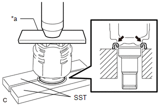
1. INSTALL REAR DRIVE SHAFT DUST COVER
| (a) Using SST, a steel plate and a press, install a new rear drive shaft dust cover. SST: 09527-21011 NOTICE:
|
|
2. INSTALL REAR DRIVE SHAFT OUTBOARD JOINT BOOT
| (a) Wrap the splines of the rear drive shaft outboard joint shaft assembly with protective tape to prevent the boot from being damaged. |
|
.png)
(b) Install new parts to the rear drive shaft outboard joint shaft assembly in the following order:
.png)
| *1 | Rear Drive Shaft Outboard Joint Shaft Assembly |
| *2 | Rear No. 2 Drive Shaft Outboard Joint Boot Clamp |
| *3 | Rear Drive Shaft Outboard Joint Boot |
| *4 | Rear Drive Shaft Outboard Joint Boot Clamp |
.png) | Outboard joint side |
.png) | Inboard joint side |
(1) Rear No. 2 drive shaft outboard joint boot clamp
(2) Rear drive shaft outboard joint boot
(3) Rear drive shaft outboard joint boot clamp
(c) Pack the joint portion of the rear drive shaft outboard joint shaft assembly and rear drive shaft outboard joint boot with grease.
Standard Grease Capacity:
50 to 60 g (1.77 to 2.11 oz)
(d) Install the rear drive shaft outboard joint boot to the rear drive shaft outboard joint shaft assembly groove.
NOTICE:
- Do not allow grease to adhere to the boot clamp track of the outboard joint boot.
- Keep the inside of the outboard joint boot free of foreign matter.
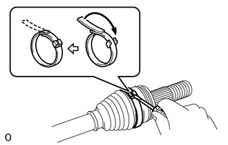
3. INSTALL REAR NO. 2 DRIVE SHAFT OUTBOARD JOINT BOOT CLAMP
| (a) Using a screwdriver, install the rear No. 2 drive shaft outboard joint boot clamp as shown in the illustration. NOTICE: Be careful not to damage the rear drive shaft outboard joint boot. |
|
4. INSTALL REAR DRIVE SHAFT OUTBOARD JOINT BOOT CLAMP
(a) Hold the drive shaft in a vise between aluminum plates.
NOTICE:
Do not overtighten the vise.
(b) Install the rear drive shaft outboard joint boot clamp to the rear drive shaft outboard joint boot.
| (c) Place SST onto the rear drive shaft outboard joint boot clamp, press it against the boot and slightly tighten SST. SST: 09521-24010 |
|
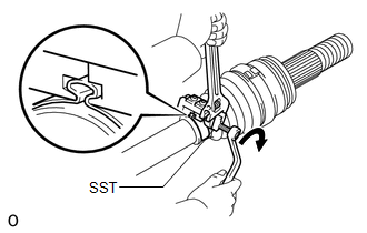
(d) Tighten SST so that the rear drive shaft outboard joint boot clamp is pinched.
NOTICE:
Do not overtighten SST.
(e) Remove SST.
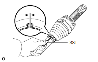
| (f) Using SST, measure the clearance of the rear drive shaft outboard joint boot clamp. SST: 09240-00020 Clearance: 0 to 1.2 mm (0 to 0.0472 in.) If the clearance is outside the specified range, retighten SST. |
|
5. INSTALL REAR DRIVE SHAFT INBOARD JOINT ASSEMBLY
(a) Install new parts to the rear drive shaft outboard joint shaft assembly in the following order:
.png)
| *1 | Rear Drive Shaft Inboard Joint Boot Clamp |
| *2 | Rear Drive Shaft Inboard Joint Boot |
| *3 | Rear No. 2 Drive Shaft Inboard Joint Boot Clamp |
| *a | Protective Tape |
| | Outboard joint side |
| | Inboard joint side |
(1) Rear drive shaft inboard joint boot clamp
(2) Rear drive shaft inboard joint boot
(3) Rear No. 2 drive shaft inboard joint boot clamp
(b) Hold the drive shaft in a vise between aluminum plates.
NOTICE:
Do not overtighten the vise.
(c) Remove the protective tape.
| (d) Align the matchmarks and install the tripod joint to the rear drive shaft outboard joint shaft assembly. NOTICE: Face the serrated side of the tripod joint outward and install it to the outboard joint end. |
|
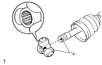
(e) Using a brass bar and a hammer, install the tripod joint to the rear drive shaft outboard joint shaft assembly.
NOTICE:
- Do not tap the rollers.
- Keep the tripod joint free of foreign matter.
- Be sure to install the tripod joint in the correct direction.
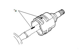
| (f) Using a snap ring expander, install a new shaft snap ring to the rear drive shaft outboard joint shaft assembly. |
|
.png)
(g) Pack the rear drive shaft inboard joint assembly and rear drive shaft inboard joint boot with grease.
Standard Grease Capacity:
93 to 103 g (3.29 to 3.63 oz)
| (h) Align the matchmarks and install the rear drive shaft inboard joint assembly to the rear drive shaft outboard joint shaft assembly. |
|
6. INSTALL REAR DRIVE SHAFT INBOARD JOINT BOOT
(a) Install the rear drive shaft inboard joint boot to the rear drive shaft inboard joint assembly.
| (b) Check whether the drive shaft dimension (A) is within specification. Dimension (A):
|
|
.png)
7. INSTALL REAR NO. 2 DRIVE SHAFT INBOARD JOINT BOOT CLAMP
(a) Hold the drive shaft in a vise between aluminum plates.
NOTICE:
Do not overtighten the vise.
| (b) Using needle-nose pliers, engage the 2 claws to install the rear No. 2 drive shaft inboard joint boot clamp as shown in the illustration (for Type A). NOTICE: Be careful not to damage the rear drive shaft inboard joint boot. |
|
.png)
(c) Using needle nose pliers, install the rear No. 2 drive shaft inboard joint boot clamp as shown in the illustration (for Type B).
NOTICE:
Be careful not to damage the rear drive shaft inboard joint boot.
8. INSTALL REAR DRIVE SHAFT INBOARD JOINT BOOT CLAMP
HINT:
Perform the same procedure as for the rear No. 2 drive shaft inboard joint boot clamp.
9. INSPECT REAR DRIVE SHAFT ASSEMBLY
Click here .gif)
 Inspection
INSPECTION PROCEDURE 1. INSPECT REAR DRIVE SHAFT ASSEMBLY (a) Check that there is no excessive play in the radial direction of the outboard joint. (b) Check that the inboard joint slide ...
 Installation
INSTALLATION CAUTION / NOTICE / HINT HINT:
Use the same procedure for the RH side and LH side.
The following procedure is for the LH side.
PROCEDURE 1. INSTALL REAR DRIVE SHAFT SNAP RING (a) I ...
Other materials:
Lexus RX (RX 350L, RX450h) 2016-2026 Repair Manual > Audio And Visual System (for 12.3 Inch Display): HD Radio Tuner Malfunction (B1551,B15A0,B15B3-B15B5,B15B7,B15F9)
DESCRIPTION These DTCs are stored when a malfunction occurs in the radio receiver assembly. DTC No. Detection Item DTC Detection Condition Trouble Area B1551 HD Radio Tuner Malfunction When any of the following conditions is met:
"HD Radio" tuner decoder malfunction
"HD Radio" ...
Lexus RX (RX 350L, RX450h) 2016-2026 Repair Manual > Dynamic Radar Cruise Control System: Road Test
ROAD TEST HINT:
The dynamic radar cruise control system has 2 cruise control modes: constant speed control mode and vehicle-to-vehicle distance control mode.
Vehicle-to-vehicle distance control mode is selected by default when the dynamic radar cruise control system is turned on using the cruis ...
Lexus RX (RX 350L, RX450h) 2016-{YEAR} Owners Manual
- For your information
- Pictorial index
- For safety and security
- Instrument cluster
- Operation of each component
- Driving
- Lexus Display Audio system
- Interior features
- Maintenance and care
- When trouble arises
- Vehicle specifications
- For owners
Lexus RX (RX 350L, RX450h) 2016-{YEAR} Repair Manual

0.01