Lexus RX (RX 350L, RX450h) 2016-2026 Repair Manual: Transmission Control Switch Circuit
DESCRIPTION
The transmission control switch detects when the shift lever is moved to M.
Moving the shift lever to "+" once selects the next higher gear, and moving the shift lever to "-" once selects the next lower gear.
WIRING DIAGRAM
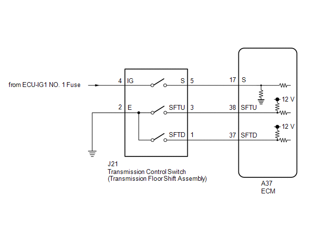
CAUTION / NOTICE / HINT
NOTICE:
Inspect the fuses for circuits related to this system before performing the following procedure.
PROCEDURE
| 1. | READ VALUE USING TECHSTREAM (Shift SW Status (S Range)) |
(a) Connect the Techstream to the DLC3.
(b) Turn the engine switch on (IG).
(c) Turn the Techstream on.
(d) Enter the following menus: Powertrain / Transmission / Data List
(e) Read the Data List according to the display on the Techstream.
Powertrain > Transmission > Data List| Tester Display | Measurement Item | Range | Normal Condition | Diagnostic Note |
|---|---|---|---|---|
| Shift SW Status (S Range) | Sport (M) mode select switch status | ON or OFF |
| - |
| Tester Display |
|---|
| Shift SW Status (S Range) |
| Result | Proceed to |
|---|---|
| Data List values are normal | A |
| Data List values are not normal | B |
| B | .gif) | GO TO STEP 6 |
|
.gif)
| 2. | READ VALUE USING TECHSTREAM (SPORT SHIFT UP SW AND SPORT SHIFT DOWN SW) |
(a) Connect the Techstream to the DLC3.
(b) Turn the engine switch on (IG).
(c) Turn the Techstream on.
(d) Enter the following menus: Powertrain / Engine / Data List
(e) Read the Data List according to the display on the Techstream.
Powertrain > Engine > Data List| Tester Display | Measurement Item | Range | Normal Condition | Diagnostic Note |
|---|---|---|---|---|
| Sport Shift Up SW | Sport shift up switch status | ON or OFF |
| - |
| Sport Shift Down SW | Sport shift down switch status | ON or OFF |
| - |
| Tester Display |
|---|
| Sport Shift Up SW |
| Sport Shift Down SW |
| Result | Proceed to |
|---|---|
| Data List values are normal | A |
| Data List values are not normal | B |
| A | | PROCEED TO NEXT SUSPECTED AREA SHOWN IN PROBLEM SYMPTOMS TABLE |
|
| 3. | INSPECT TRANSMISSION CONTROL SWITCH (TRANSMISSION FLOOR SHIFT ASSEMBLY) |
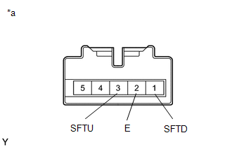
(a) Disconnect the J21 transmission control switch connector.
| (b) Measure the resistance according to the value(s) in the table below. Standard Resistance:
|
|
| NG | | REPLACE TRANSMISSION FLOOR SHIFT ASSEMBLY (TRANSMISSION CONTROL SWITCH) |
|
| 4. | CHECK HARNESS AND CONNECTOR (TRANSMISSION CONTROL SWITCH - BODY GROUND) |
(a) Disconnect the J21 transmission control switch connector.
(b) Measure the resistance according to the value(s) in the table below.
Standard Resistance:
| Tester Connection | Condition | Specified Condition |
|---|---|---|
| J21-2 (E) - Body ground | Always | Below 1 Ω |
| NG | | REPAIR OR REPLACE HARNESS OR CONNECTOR |
|
| 5. | CHECK HARNESS AND CONNECTOR (TRANSMISSION CONTROL SWITCH - ECM) |
(a) Connect the J21 transmission floor shift assembly (transmission control switch) connector.
(b) Disconnect the A37 ECM connector.
(c) Disconnect the spiral cable sub-assembly connector.
(d) Measure the resistance according to the value(s) in the table below.
Standard Resistance:
| Tester Connection | Condition | Specified Condition |
|---|---|---|
| A37-38 (SFTU) - Body ground | Shift lever held in "+" (Up shift) | Below 1 Ω |
| Shift lever not held in "+" (Up shift) | 10 kΩ or higher | |
| A37-37 (SFTD) - Body ground | Shift lever held in "-" (Down shift) | Below 1 Ω |
| Shift lever not held in "-" (Down shift) | 10 kΩ or higher |
| OK | | PROCEED TO NEXT SUSPECTED AREA SHOWN IN PROBLEM SYMPTOMS TABLE |
| NG | | REPAIR OR REPLACE HARNESS OR CONNECTOR (TRANSMISSION CONTROL SWITCH - ECM) |
| 6. | INSPECT TRANSMISSION CONTROL SWITCH (TRANSMISSION FLOOR SHIFT ASSEMBLY) |
| (a) Disconnect the J21 transmission control switch connector. |
|
(b) Measure the resistance according to the value(s) in the table below.
Standard Resistance:
| Tester Connection | Condition | Specified Condition |
|---|---|---|
| 4 (IG) - 5 (S) | Shift lever in M, "+" or "-" | Below 1 Ω |
| Shift lever not in M, "+" or "-" | 10 kΩ or higher |
| NG | | REPLACE TRANSMISSION FLOOR SHIFT ASSEMBLY (TRANSMISSION CONTROL SWITCH) |
|
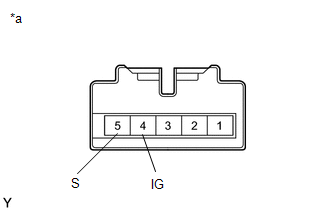
| 7. | CHECK HARNESS AND CONNECTOR (TRANSMISSION CONTROL SWITCH (POWER SOURCE)) |
(a) Disconnect the J21 transmission control switch connector.
(b) Turn the engine switch on (IG).
(c) Measure the voltage according to the value(s) in the table below.
Standard Voltage:
| Tester Connection | Condition | Specified Condition |
|---|---|---|
| J21-4 (IG) - Body ground | Engine switch on (IG) | 11 to 14 V |
| NG | | REPAIR OR REPLACE HARNESS OR CONNECTOR |
|
| 8. | CHECK HARNESS AND CONNECTOR (TRANSMISSION CONTROL SWITCH - ECM) |
(a) Disconnect the J21 transmission control switch connector.
(b) Disconnect the A37 ECM connector.
(c) Measure the resistance according to the value(s) in the table below.
Standard Resistance:
| Tester Connection | Condition | Specified Condition |
|---|---|---|
| J21-5 (S) - A37-17 (S) | Always | Below 1 Ω |
| J21-5 (S) or A37-17 (S) - Body ground and other terminals | Always | 10 kΩ or higher |
| OK | | PROCEED TO NEXT SUSPECTED AREA SHOWN IN PROBLEM SYMPTOMS TABLE |
| NG | | REPAIR OR REPLACE HARNESS OR CONNECTOR |
 Lost Communication with ECM/PCM "A" Missing Message (U010087)
DESCRIPTION The engine control unit and transmission control unit are located inside the ECM. The engine control unit intercommunicates with the transmission control unit using CAN communication. If t ...
 Shift Paddle Switch Circuit
DESCRIPTION When the shift lever is in D, operating the "-" (down shift) shift paddle switch will cause the transaxle to enter fixed range mode which restricts the highest gear. By operating the "+" ( ...
Other materials:
Lexus RX (RX 350L, RX450h) 2016-2026 Repair Manual > Maintenance: Engine
General MaintenanceGENERAL MAINTENANCE CAUTION / NOTICE / HINT HINT: Perform these procedures after the engine has cooled down. PROCEDURE 1. INSPECT DRIVE BELT (a) Check the drive belt. for 2GR-FKS: Click here 2. INSPECT ENGINE OIL AND OIL FILTER (a) Check the engine oil and oil filter. for 2GR-FK ...
Lexus RX (RX 350L, RX450h) 2016-2026 Repair Manual > Electric Parking Brake System: Left Electric Parking Brake Actuator Signal Stuck In Range (C060E2A)
DESCRIPTION DTC No. Detection Item DTC Detection Condition Trouble Area Memory Note C060E2A Left Electric Parking Brake Actuator Signal Stuck In Range
Diagnosis Condition:
Electric parking brake operating
Malfunction Status:
Motor locked, gear locked, free spinning
Detect ...
Lexus RX (RX 350L, RX450h) 2016-{YEAR} Owners Manual
- For your information
- Pictorial index
- For safety and security
- Instrument cluster
- Operation of each component
- Driving
- Lexus Display Audio system
- Interior features
- Maintenance and care
- When trouble arises
- Vehicle specifications
- For owners
Lexus RX (RX 350L, RX450h) 2016-{YEAR} Repair Manual

0.0099