
Lexus RX (RX 350L, RX450h) 2016-2026 Repair Manual: Shift Paddle Switch Circuit
DESCRIPTION
When the shift lever is in D, operating the "-" (down shift) shift paddle switch will cause the transaxle to enter fixed range mode which restricts the highest gear. By operating the "+" (up shift) or "-" (down shift) shift paddle switch, the gear can be changed.
When the vehicle is being driven with the shift lever in D (fixed range mode), if the vehicle is stopped or the accelerator pedal is kept steady for a certain period of time with the transaxle in the same gear, the vehicle will change back automatically to normal D position operation.
When the shift lever is in M, it is possible to make use of the highest engine speeds by holding the vehicle in a gear. Gear hold control means that gear shifts will not be performed as long as the "+" (up shift), or "-" (down shift) shift paddle switch is not operated.
WIRING DIAGRAM
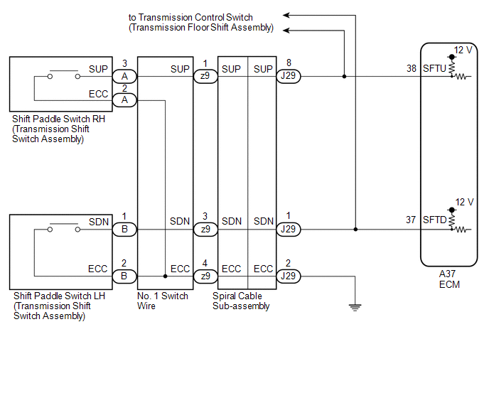
PROCEDURE
| 1. | READ VALUE USING TECHSTREAM (SPORT SHIFT SWITCH STATUS) |
(a) Connect the Techstream to the DLC3.
(b) Turn the engine switch on (IG).
(c) Turn the Techstream on.
(d) Enter the following menus: Powertrain / Engine / Data List.
(e) Read the Data List according to the display on the Techstream.
Powertrain > Engine > Data List| Tester Display | Measurement Item | Range | Normal Condition | Diagnostic Note |
|---|---|---|---|---|
| Sport Shift Up SW | Sport shift up switch status | ON or OFF |
| - |
| Sport Shift Down SW | Sport shift down switch status | ON or OFF |
| - |
| Tester Display |
|---|
| Sport Shift Up SW |
| Sport Shift Down SW |
| Result | Proceed to |
|---|---|
| Data List values are not normal | A |
| Data List values are normal | B |
| B | .gif) | CHECK FOR INTERMITTENT PROBLEMS |
|
.gif)
| 2. | CHECK HARNESS AND CONNECTOR (SHIFT PADDLE SWITCH - ECM) |
(a) Disconnect the A37 ECM connector.
(b) Measure the resistance according to the value(s) in the table below.
Standard Resistance:
| Tester Connection | Condition | Specified Condition |
|---|---|---|
| A37-38 (SFTU) - Body ground | "+" (Up shift) shift paddle switch operated and held | Below 2.5 Ω |
| "+" (Up shift) shift paddle switch not operated | 1 MΩ or higher | |
| A37-37 (SFTD) - Body ground | "-" (Down shift) shift paddle switch operated and held | Below 2.5 Ω |
| "-" (Down shift) shift paddle switch not operated | 1 MΩ or higher |
| OK | | PROCEED TO NEXT SUSPECTED AREA SHOWN IN PROBLEM SYMPTOMS TABLE |
|
| 3. | CHECK HARNESS AND CONNECTOR (SPIRAL CABLE SUB-ASSEMBLY - ECM) |
(a) Disconnect the J29 spiral cable sub-assembly connector.
(b) Disconnect the A37 ECM connector.
(c) Measure the resistance according to the value(s) in the table below.
Standard Resistance:
| Tester Connection | Condition | Specified Condition |
|---|---|---|
| A37-38 (SFTU) - J29-8 (SUP) | Always | Below 1 Ω |
| A37-37 (SFTD) - J29-1 (SDN) | Always | Below 1 Ω |
| A37-38 (SFTU) or J29-8 (SUP) - Body ground | Always | 10 kΩ or higher |
| A37-37 (SFTD) or J29-1 (SDN) - Body ground | Always | 10 kΩ or higher |
| NG | | REPAIR OR REPLACE HARNESS OR CONNECTOR |
|
| 4. | CHECK HARNESS AND CONNECTOR (SPIRAL CABLE SUB-ASSEMBLY - BODY GROUND) |
(a) Disconnect the J29 spiral cable sub-assembly connector.
(b) Measure the resistance according to the value(s) in the table below.
Standard Resistance:
| Tester Connection | Condition | Specified Condition |
|---|---|---|
| J29-2 (ECC) - Body ground | Always | Below 1 Ω |
| NG | | REPAIR OR REPLACE HARNESS OR CONNECTOR |
|
| 5. | INSPECT SPIRAL CABLE SUB-ASSEMBLY |
(a) Inspect the spiral cable sub-assembly.
Click here .gif)
| NG | | REPLACE SPIRAL CABLE SUB-ASSEMBLY |
|
| 6. | INSPECT TRANSMISSION SHIFT SWITCH ASSEMBLY (SHIFT PADDLE SWITCH LH) |
| (a) Remove the transmission shift switch assembly (shift paddle switch LH). Click here |
|
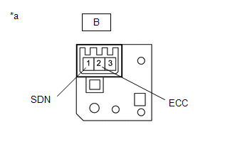
(b) Measure the resistance according to the value(s) in the table below.
Standard Resistance:
| Tester Connection | Condition | Specified Condition |
|---|---|---|
| B-1 (SDN) - B-2 (ECC) | "-" (Down shift) shift paddle switch operated and held | Below 2.5 Ω |
| "-" (Down shift) shift paddle switch not operated | 1 MΩ or higher |
| NG | | REPLACE TRANSMISSION SHIFT SWITCH ASSEMBLY (SHIFT PADDLE SWITCH LH) |
|
| 7. | INSPECT TRANSMISSION SHIFT SWITCH ASSEMBLY (SHIFT PADDLE SWITCH RH) |
| (a) Remove the transmission shift switch assembly (shift paddle switch RH). Click here |
|
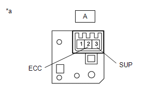
(b) Measure the resistance according to the value(s) in the table below.
Standard Resistance:
| Tester Connection | Condition | Specified Condition |
|---|---|---|
| A-3 (SUP) - A-2 (ECC) | "+" (Up shift) shift paddle switch operated and held | Below 2.5 Ω |
| "+" (Up shift) shift paddle switch not operated | 1 MΩ or higher |
| NG | | REPLACE TRANSMISSION SHIFT SWITCH ASSEMBLY (SHIFT PADDLE SWITCH RH) |
|
| 8. | INSPECT NO. 1 SWITCH WIRE |
| (a) Install the transmission shift switch assembly. Click here |
|
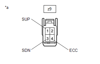
(b) Disconnect the z9 No. 1 switch wire connector from the spiral cable sub-assembly.
(c) Measure the resistance according to the value(s) in the table below.
Standard Resistance:
| Tester Connection | Condition | Specified Condition |
|---|---|---|
| z9-1 (SUP) - z9-4 (ECC) | "+" (Up shift) shift paddle switch operated and held | Below 2.5 Ω |
| "+" (Up shift) shift paddle switch not operated | 1 MΩ or higher | |
| z9-3 (SDN) - z9-4 (ECC) | "-" (Down shift) shift paddle switch operated and held | Below 2.5 Ω |
| "-" (Down shift) shift paddle switch not operated | 1 MΩ or higher |
| OK | | PROCEED TO NEXT SUSPECTED AREA SHOWN IN PROBLEM SYMPTOMS TABLE |
| NG | | REPLACE NO. 1 SWITCH WIRE |
 Transmission Control Switch Circuit
DESCRIPTION The transmission control switch detects when the shift lever is moved to M. Moving the shift lever to "+" once selects the next higher gear, and moving the shift lever to "-" once selects ...

Other materials:
Lexus RX (RX 350L, RX450h) 2016-2026 Repair Manual > Audio And Visual System (for 12.3 Inch Display): Vehicle Speed Signal Circuit between Navigation ECU and Combination Meter
DESCRIPTION The navigation ECU receives a vehicle speed signal from the combination meter assembly. HINT:
A voltage of 12 V or 5 V is output from each ECU and then input to the combination meter assembly. The signal is changed to a pulse signal at the transistor in the combination meter assembly. ...
Lexus RX (RX 350L, RX450h) 2016-2026 Repair Manual > Front Brake Flexible Hose: Components
COMPONENTS ILLUSTRATION *1 FRONT FLEXIBLE HOSE *2 UNION BOLT *3 GASKET *4 BRAKE LINE *5 FRONT SPEED SENSOR - - Tightening torque for "Major areas involving basic vehicle performance such as moving/turning/stopping" : N*m (kgf*cm, ft.*lbf) N*m (kgf*cm, ft.*lb ...
Lexus RX (RX 350L, RX450h) 2016-{YEAR} Owners Manual
- For your information
- Pictorial index
- For safety and security
- Instrument cluster
- Operation of each component
- Driving
- Lexus Display Audio system
- Interior features
- Maintenance and care
- When trouble arises
- Vehicle specifications
- For owners
Lexus RX (RX 350L, RX450h) 2016-{YEAR} Repair Manual

0.0104