Lexus RX (RX 350L, RX450h) 2016-2026 Repair Manual: Terminals Of Ecu
TERMINALS OF ECU
NOTICE:
-
After turning the engine switch off, waiting time may be required before disconnecting the cable from the negative (-) battery terminal. Therefore, make sure to read the disconnecting the cable from the negative (-) battery terminal notices before proceeding with work.
Click here
.gif)
- Turn the engine switch off before measuring the resistances between CAN main bus lines and between CAN branch lines.
- Turn the engine switch off before inspecting CAN bus lines for a short to ground.
- Before measuring the resistance of the CAN bus, turn the engine switch off and leave the vehicle for 1 minute or more without operating the key or any switches, or opening or closing the doors. After that, disconnect the cable from the negative (-) battery terminal and leave the vehicle for 1 minute or more before measuring the resistance.
- This section describes the standard values for all CAN related components.
HINT:
- Operating the engine switch, any other switches or a door triggers related ECU and sensor communication on the CAN. This communication will cause the resistance value to change.
- Even after DTCs are cleared, if a DTC is stored again after driving the vehicle for a while, the malfunction may be occurring due to vibration of the vehicle. In such a case, wiggling the ECUs or wire harness while performing the inspection below may help determine the cause of the malfunction.
NO. 1 CAN JUNCTION CONNECTOR
(a) Check the No. 1 CAN junction connector.
(1) Connection diagram
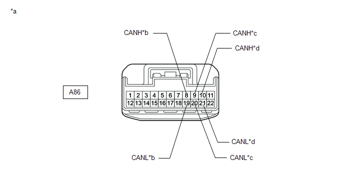
| *a | Front view of wire harness connector (to No. 1 CAN Junction Connector) | *b | to No. 8 CAN Junction Connector (for Bus 4) |
| *c | to Network Gateway ECU (for Bus 4) | *d | to Skid Control ECU (Brake Actuator Assembly) (for Bus 4) |
(2) Check the connection diagram of the components which are connected to the No. 1 CAN junction connector.
| Terminal No. (Symbol) | Wiring Color | Connected to |
|---|---|---|
| A86-8 (CANH) | SB | No. 8 CAN junction connector (for bus 4) |
| A86-19 (CANL) | W | |
| A86-9 (CANH) | GR | Network gateway ECU (for bus 4) |
| A86-20 (CANL) | W | |
| A86-10 (CANH) | B | Skid control ECU (brake actuator assembly) (for bus 4) |
| A86-21 (CANL) | W |
NO. 3 CAN JUNCTION CONNECTOR
(a) Check the No. 3 CAN junction connector.
(1) Connection diagram
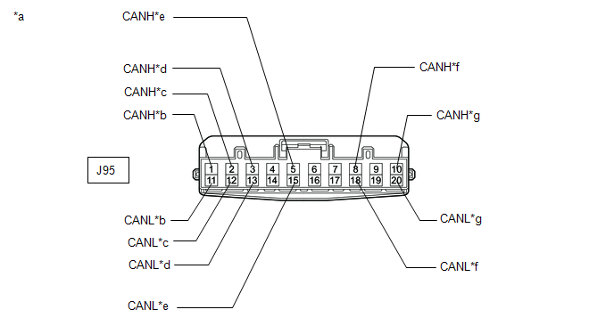
| *a | Front view of wire harness connector (to No. 3 CAN Junction Connector) | *b | to Network Gateway ECU (for Bus 1) |
| *c | to Parking Assist ECU (w/ Panoramic View Monitor System) (for Bus 1) | *d | to Clearance Warning ECU Assembly (w/ Intuitive Parking Assist System) (for Bus 1) |
| *e | to Millimeter Wave Radar Sensor Assembly (for Bus 1) | *f | to Forward Recognition Camera (for Bus 1) |
| *g | to No. 10 CAN Junction Connector (for Bus 1) | - | - |
(2) Check the connection diagram of the components which are connected to the No. 3 CAN junction connector.
| Terminal No. (Symbol) | Wiring Color | Connected to |
|---|---|---|
| J95-1 (CANH) | GR | Network gateway ECU (for bus 1) |
| J95-11 (CANL) | W | |
| J95-2 (CANH) | LG | Parking assist ECU*1 (for bus 1) |
| J95-12 (CANL) | W | |
| J95-3 (CANH) | L | Clearance warning ECU assembly*2 (for bus 1) |
| J95-13 (CANL) | W | |
| J95-5 (CANH) | G | Millimeter wave radar sensor assembly (for bus 1) |
| J95-15 (CANL) | W | |
| J95-8 (CANH) | R | Forward recognition camera (for bus 1) |
| J95-18 (CANL) | W | |
| J95-10 (CANH) | Y | No. 10 CAN junction connector (for bus 1) |
| J95-20 (CANL) | W |
- *1: w/ Panoramic View Monitor System
- *2: w/ Intuitive Parking Assist System
NO. 5 CAN JUNCTION CONNECTOR
(a) Check the No. 5 CAN junction connector.
(1) Connection diagram
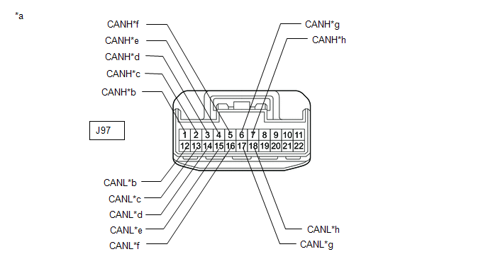
| *a | Front view of wire harness connector (to No. 5 CAN Junction Connector) | *b | to Network Gateway ECU (for Bus 5) |
| *c | to Combination Meter Mirror ECU (Headup Display) (w/ Headup Display System) (for Bus 5) | *d | to Headlight ECU Sub-assembly LH (w/ Automatic Headlight Beam Level Control System) (for Bus 5) |
| *e | to Main Body ECU (Multiplex Network Body ECU) (for Bus 5) | *f | to Air Conditioning Amplifier Assembly (for Bus 5) |
| *g | to Combination Meter Assembly (for Bus 5) | *h | to Certification ECU (Smart Key ECU Assembly) (for Bus 5) |
(2) Check the connection diagram of the components which are connected to the No. 5 CAN junction connector.
| Terminal No. (Symbol) | Wiring Color | Connected to |
|---|---|---|
| J97-1 (CANH) | B | Network gateway ECU (for bus 5) |
| J97-12 (CANL) | W | |
| J97-2 (CANH) | P | Combination meter mirror ECU (headup display)*1 (for bus 5) |
| J97-13 (CANL) | W | |
| J97-3 (CANH) | Y | Headlight ECU sub-assembly LH*2 (for bus 5) |
| J97-14 (CANL) | W | |
| J97-4 (CANH) | L | Main body ECU (multiplex network body ECU) (for bus 5) |
| J97-15 (CANL) | W | |
| J97-5 (CANH) | LG | Air conditioning amplifier assembly (for bus 5) |
| J97-16 (CANL) | W | |
| J97-6 (CANH) | GR | Combination meter assembly (for bus 5) |
| J97-17 (CANL) | W | |
| J97-7 (CANH) | P | Certification ECU (smart key ECU assembly) (for bus 5) |
| J97-18 (CANL) | W |
- *1: w/ Headup Display System
- *2: w/ Automatic Headlight Beam Level Control System
NO. 6 CAN JUNCTION CONNECTOR
(a) Check the No. 6 CAN junction connector.
(1) Connection diagram
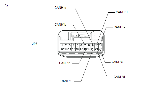
| *a | Front view of wire harness connector (to No. 6 CAN Junction Connector) | *b | to Network Gateway ECU (for Bus 3) |
| *c | to DCM (Telematics Transceiver) (w/ Manual (SOS) Switch) (for Bus 3) | *d | to Radio Receiver Assembly (for Bus 3) |
| *e | to Network Gateway ECU (for Bus 3) | - | - |
(2) Check the connection diagram of the components which are connected to the No. 6 CAN junction connector.
| Terminal No. (Symbol) | Wiring Color | Connected to |
|---|---|---|
| J98-7 (CANH) | Y | Network gateway ECU (for bus 3) |
| J98-18 (CANL) | W | |
| J98-9 (CANH) | L | DCM (telematics transceiver)* (for bus 3) |
| J98-20 (CANL) | W | |
| J98-10 (CANH) | BE | Radio receiver assembly (for bus 3) |
| J98-21 (CANL) | W | |
| J98-11 (CANH) | SB | Network gateway ECU (for bus 3) |
| J98-22 (CANL) | W |
- *: w/ Manual (SOS) Switch
NO. 7 CAN JUNCTION CONNECTOR
(a) Check the No. 7 CAN junction connector.
(1) Connection diagram
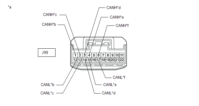
| *a | Front view of wire harness connector (to No. 7 CAN Junction Connector) | *b | to Airbag Sensor Assembly (for Bus 4) |
| *c | to Steering Sensor (for Bus 4) | *d | to Yaw Rate Sensor Assembly (w/ TFT Meter Type Combination Meter Assembly) (for Bus 4) |
| *e | to Power Steering ECU Assembly (for Bus 4) | *f | to No. 12 CAN Junction Connector (for Bus 4) |
(2) Check the connection diagram of the components which are connected to the No. 7 CAN junction connector.
| Terminal No. (Symbol) | Wiring Color | Connected to |
|---|---|---|
| J99-1 (CANH) | B | Airbag sensor assembly (for bus 4) |
| J99-12 (CANL) | W | |
| J99-2 (CANH) | R | Steering sensor (for bus 4) |
| J99-13 (CANL) | W | |
| J99-3 (CANH) | P | Yaw rate sensor assembly* (for bus 4) |
| J99-14 (CANL) | W | |
| J99-4 (CANH) | GR | Power steering ECU assembly (for bus 4) |
| J99-15 (CANL) | W | |
| J99-6 (CANH) | LG | No. 12 CAN junction connector (for bus 4) |
| J99-17 (CANL) | W |
- *: w/ TFT Meter Type Combination Meter Assembly
NO. 8 CAN JUNCTION CONNECTOR
(a) Check the No. 8 CAN junction connector.
(1) Connection diagram
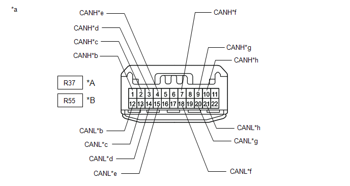
| *A | w/o Rear No. 2 Seat | *B | w/ Rear No. 2 Seat |
| *a | Front view of wire harness connector (to No. 8 CAN Junction Connector) | *b | to No. 9 CAN Junction Connector (for Bus 4) |
| *c | to No. 1 CAN Junction Connector (for Bus 4) | *d | to Occupant Detection ECU (for Bus 4) |
| *e | to 4WD ECU Assembly (for AWD) (for Bus 4) | *f | to No. 11 CAN Junction Connector (for Sub Bus 1) |
| *g | to No. 1 CAN Junction Terminal (for Sub Bus 1) | *h | to Outer Mirror Control ECU Assembly (for Front Passenger Side) (for Sub Bus 1) |
(2) Check the connection diagram of the components which are connected to the No. 8 CAN junction connector.
w/o Rear No. 2 Seat| Terminal No. (Symbol) | Wiring Color | Connected to |
|---|---|---|
| R37-1 (CANH) | B | No. 9 CAN junction connector (for bus 4) |
| R37-12 (CANL) | W | |
| R37-2 (CANH) | LG | No. 1 CAN junction connector (for bus 4) |
| R37-13 (CANL) | W | |
| R37-3 (CANH) | B | Occupant detection ECU (for bus 4) |
| R37-14 (CANL) | W | |
| R37-4 (CANH) | B | 4WD ECU assembly*1 (for bus 4) |
| R37-15 (CANL) | W | |
| R37-7 (CANH) | W | No. 11 CAN junction connector (for sub bus 1) |
| R37-18 (CANL) | B | |
| R37-9 (CANH) | W | No. 1 CAN junction terminal (for sub bus 1) |
| R37-20 (CANL) | R | |
| R37-10 (CANH) | W*2 | Outer mirror control ECU assembly (for front passenger side) (for sub bus 1) |
| P*3 | ||
| R37-21 (CANL) | B*2 | |
| LG*3 |
| Terminal No. (Symbol) | Wiring Color | Connected to |
|---|---|---|
| R55-1 (CANH) | B | No. 9 CAN junction connector (for bus 4) |
| R55-12 (CANL) | W | |
| R55-2 (CANH) | LG | No. 1 CAN junction connector (for bus 4) |
| R55-13 (CANL) | W | |
| R55-3 (CANH) | B | Occupant detection ECU (for bus 4) |
| R55-14 (CANL) | W | |
| R55-4 (CANH) | B | 4WD ECU assembly*1 (for bus 4) |
| R55-15 (CANL) | W | |
| R55-7 (CANH) | W | No. 11 CAN junction connector (for sub bus 1) |
| R55-18 (CANL) | B | |
| R55-9 (CANH) | W | No. 1 CAN junction terminal (for sub bus 1) |
| R55-20 (CANL) | R | |
| R55-10 (CANH) | P | Outer mirror control ECU assembly (for front passenger side) (for sub bus 1) |
| R55-21 (CANL) | LG |
- *1: for AWD
- *2: for TMMC Made
- *3: except TMMC Made
NO. 9 CAN JUNCTION CONNECTOR
(a) Check the No. 9 CAN junction connector.
(1) Connection diagram
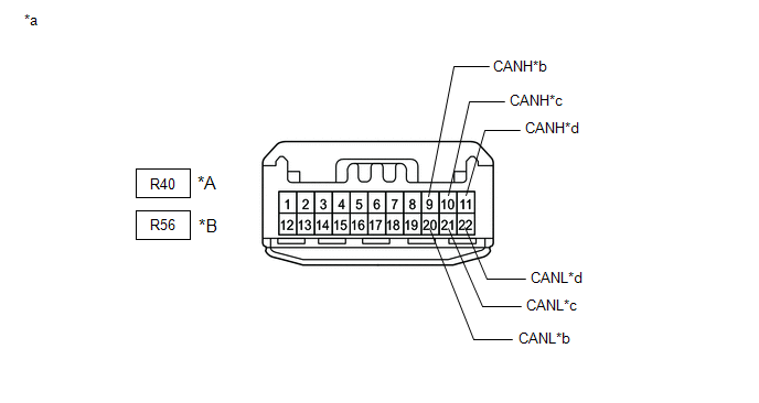
| *A | w/o Rear No. 2 Seat | *B | w/ Rear No. 2 Seat |
| *a | Front view of wire harness connector (to No. 9 CAN Junction Connector) | *b | to No. 12 CAN Junction Connector (for Bus 4) |
| *c | to Tire Pressure Warning ECU and Receiver (for Bus 4) | *d | to No. 8 CAN Junction Connector (for Bus 4) |
(2) Check the connection diagram of the components which are connected to the No. 9 CAN junction connector.
w/o Rear No. 2 Seat| Terminal No. (Symbol) | Wiring Color | Connected to |
|---|---|---|
| R40-9 (CANH) | L | No. 12 CAN junction connector (for bus 4) |
| R40-20 (CANL) | W | |
| R40-10 (CANH) | R | Tire pressure warning ECU and receiver (for bus 4) |
| R40-21 (CANL) | W | |
| R40-11 (CANH) | B | No. 8 CAN junction connector (for bus 4) |
| R40-22 (CANL) | W |
| Terminal No. (Symbol) | Wiring Color | Connected to |
|---|---|---|
| R56-9 (CANH) | L | No. 12 CAN junction connector (for bus 4) |
| R56-20 (CANL) | W | |
| R56-10 (CANH) | R | Tire pressure warning ECU and receiver (for bus 4) |
| R56-21 (CANL) | W | |
| R56-11 (CANH) | B | No. 8 CAN junction connector (for bus 4) |
| R56-22 (CANL) | W |
NO. 10 CAN JUNCTION CONNECTOR
(a) Check the No. 10 CAN junction connector.
HINT:
Connectors that connect to the CAN junction connector can be distinguished by the color of their CAN bus lines. When the connectors have been disconnected from the CAN junction connector, reconnecting the connectors to non-original positions on the CAN junction connector does not affect system performance. However, it is preferred to reconnect the connectors to their original positions to avoid negative effects on the wiring such as tension on the wire harnesses, and to make future maintenance easier.
(1) Connection diagram
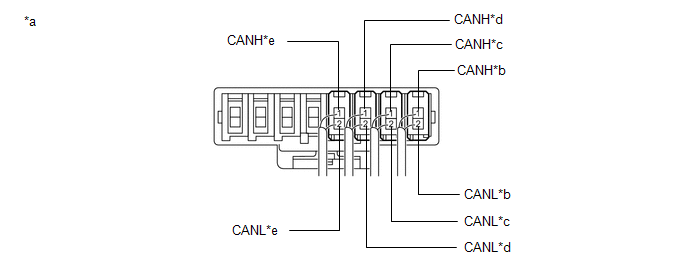
| *a | Component with harness connected (No. 10 CAN Junction Connector) | *b | to Network Gateway ECU (for Bus 1) |
| *c | to No. 3 CAN Junction Connector (for Bus 1) | *d | to Blind Spot Monitor Sensor LH (w/ Blind Spot Monitor System) (for Bus 1) |
| *e | to Rear Television Camera Assembly (for Bus 1) | - | - |
(2) Check the connection diagram of the components which are connected to the No. 10 CAN junction connector.
| Terminal No. (Symbol) | Wiring Color | Connected to |
|---|---|---|
| S56-1 (CANH) | G | Network gateway ECU (for bus 1) |
| S56-2 (CANL) | W | |
| S57-1 (CANH) | LG | No. 3 CAN junction connector (for bus 1) |
| S57-2 (CANL) | W | |
| S58-1 (CANH) | V | Blind spot monitor sensor LH* (for bus 1) |
| S58-2 (CANL) | W | |
| S59-1 (CANH) | P | Rear television camera assembly (for bus 1) |
| S59-2 (CANL) | W |
- *: w/ Blind Spot Monitor System
NO. 11 CAN JUNCTION CONNECTOR
(a) Check the No. 11 CAN junction connector.
(1) Connection diagram
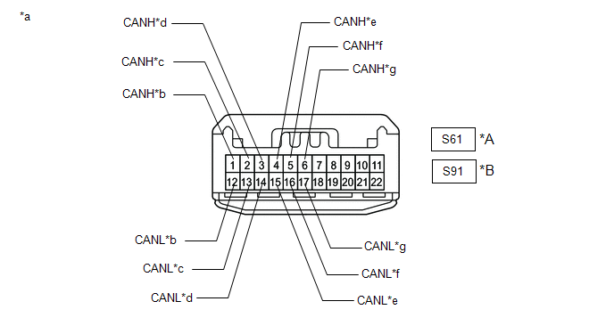
| *A | w/o Rear No. 2 Seat | *B | w/ Rear No. 2 Seat |
| *a | Front view of wire harness connector (to No. 11 CAN Junction Connector) | *b | to No. 8 CAN Junction Connector (for Sub Bus 1) |
| *c | to Multiplex Tilt and Telescopic ECU (for Sub Bus 1) | *d | to Main Body ECU (Multiplex Network Body ECU) (for Sub Bus 1) |
| *e | to Position Control ECU and Switch Assembly LH (w/ Seat Position Memory System) (for Sub Bus 1) | *f | to Multiplex Network Door ECU (for Sub Bus 1) |
| *g | to Outer Mirror Control ECU Assembly (for Driver Side) (for Sub Bus 1) | - | - |
(2) Check the connection diagram of the components which are connected to the No. 11 CAN junction connector.
w/o Rear No. 2 Seat| Terminal No. (Symbol) | Wiring Color | Connected to |
|---|---|---|
| S61-1 (CANH) | W | No. 8 CAN junction connector (for sub bus 1) |
| S61-12 (CANL) | B | |
| S61-2 (CANH) | W | Multiplex tilt and telescopic ECU (for sub bus 1) |
| S61-13 (CANL) | V | |
| S61-3 (CANH) | W | Main body ECU (multiplex network body ECU) (for sub bus 1) |
| S61-14 (CANL) | R | |
| S61-4 (CANH) | W | Position control ECU and switch assembly LH* (for sub bus 1) |
| S61-15 (CANL) | B | |
| S61-5 (CANH) | W | Multiplex network door ECU (for sub bus 1) |
| S61-16 (CANL) | L | |
| S61-6 (CANH) | W | Outer mirror control ECU assembly (for driver side) (for sub bus 1) |
| S61-17 (CANL) | G |
| Terminal No. (Symbol) | Wiring Color | Connected to |
|---|---|---|
| S91-1 (CANH) | W | No. 8 CAN junction connector (for sub bus 1) |
| S91-12 (CANL) | B | |
| S91-2 (CANH) | W | Multiplex tilt and telescopic ECU (for sub bus 1) |
| S91-13 (CANL) | V | |
| S91-3 (CANH) | W | Main body ECU (multiplex network body ECU) (for sub bus 1) |
| S91-14 (CANL) | R | |
| S91-4 (CANH) | W | Position control ECU and switch assembly LH* (for sub bus 1) |
| S91-15 (CANL) | B | |
| S91-5 (CANH) | W | Multiplex network door ECU (for sub bus 1) |
| S91-16 (CANL) | L | |
| S91-6 (CANH) | W | Outer mirror control ECU assembly (for driver side) (for sub bus 1) |
| S91-17 (CANL) | G |
- *: w/ Seat Position Memory System
NO. 12 CAN JUNCTION CONNECTOR
(a) Check the No. 12 CAN junction connector.
(1) Connection diagram
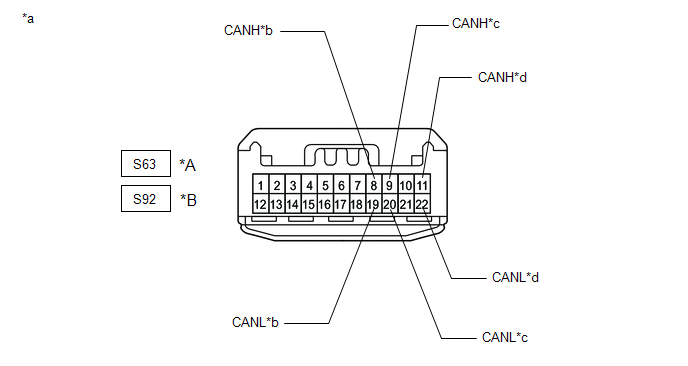
| *A | w/o Rear No. 2 Seat | *B | w/ Rear No. 2 Seat |
| *a | Front view of wire harness connector (to No. 12 CAN Junction Connector) | *b | to No. 7 CAN Junction Connector (for Bus 4) |
| *c | to No. 9 CAN Junction Connector (for Bus 4) | *d | to Absorber Control ECU (w/ AVS) (for Bus 4) |
(2) Check the connection diagram of the components which are connected to the No. 12 CAN junction connector.
w/o Rear No. 2 Seat| Terminal No. (Symbol) | Wiring Color | Connected to |
|---|---|---|
| S63-8 (CANH) | L | No. 7 CAN junction connector (for bus 4) |
| S63-19 (CANL) | W | |
| S63-9 (CANH) | G | No. 9 CAN junction connector (for bus 4) |
| S63-20 (CANL) | W | |
| S63-11 (CANH) | R | Absorber control ECU* (for bus 4) |
| S63-22 (CANL) | W |
| Terminal No. (Symbol) | Wiring Color | Connected to |
|---|---|---|
| S92-8 (CANH) | L | No. 7 CAN junction connector (for bus 4) |
| S92-19 (CANL) | W | |
| S92-9 (CANH) | G | No. 9 CAN junction connector (for bus 4) |
| S92-20 (CANL) | W | |
| S92-11 (CANH) | R | Absorber control ECU* (for bus 4) |
| S92-22 (CANL) | W |
- *: w/ AVS
NO. 1 CAN JUNCTION TERMINAL
(a) Check the No. 1 CAN junction terminal.
(1) Connection diagram
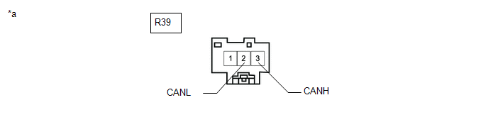
| *a | Front view of wire harness connector (to No. 1 CAN Junction Terminal) | - | - |
(2) Check the connection diagram of the components which are connected to the No. 1 CAN junction terminal.
| Terminal No. (Symbol) | Wiring Color | Connected to |
|---|---|---|
| R39-3 (CANH) | W | No. 8 CAN junction connector (for sub bus 1) |
| R39-2 (CANL) | R |
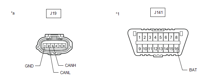
DLC3
(a) Disconnect the cable from the negative (-) battery terminal.
(b) Measure the resistance according to the value(s) in the table below.
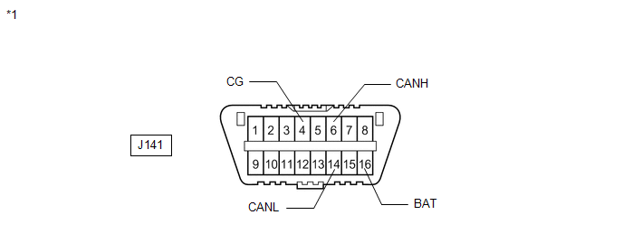
| *1 | DLC3 | - | - |
Standard Resistance:
| Terminal No. (Symbol) | Wiring Color | Terminal Description | Condition | Specified Condition |
|---|---|---|---|---|
| J141-6 (CANH) - J141-14 (CANL) | R - W | HIGH-level CAN bus line - LOW-level CAN bus line | Cable disconnected from negative (-) battery terminal | 54 to 69 Ω |
| J141-6 (CANH) - J141-4 (CG) | R - W-B | HIGH-level CAN bus line - Ground | Cable disconnected from negative (-) battery terminal | 200 Ω or higher |
| J141-14 (CANL) - J141-4 (CG) | W - W-B | LOW-level CAN bus line - Ground | Cable disconnected from negative (-) battery terminal | 200 Ω or higher |
| J141-6 (CANH) - J141-16 (BAT) | R - LG | HIGH-level CAN bus line - Battery positive (+) | Cable disconnected from negative (-) battery terminal | 6 kΩ or higher |
| J141-14 (CANL) - J141-16 (BAT) | W - LG | LOW-level CAN bus line - Battery positive (+) | Cable disconnected from negative (-) battery terminal | 6 kΩ or higher |
NETWORK GATEWAY ECU
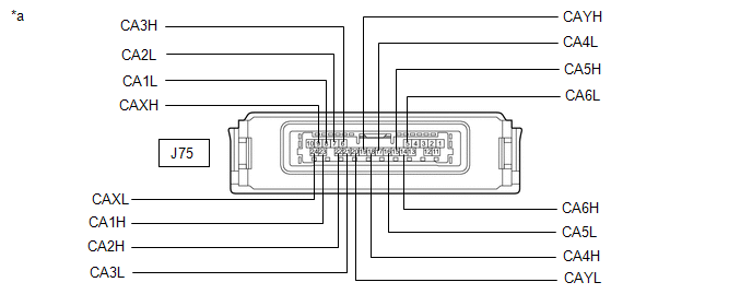
| *a | Component without harness connected (Network Gateway ECU) | - | - |
(a) Disconnect the cable from the negative (-) battery terminal.
(b) Disconnect the J75 network gateway ECU connector.
(c) Measure the resistance according to the value(s) in the table below.
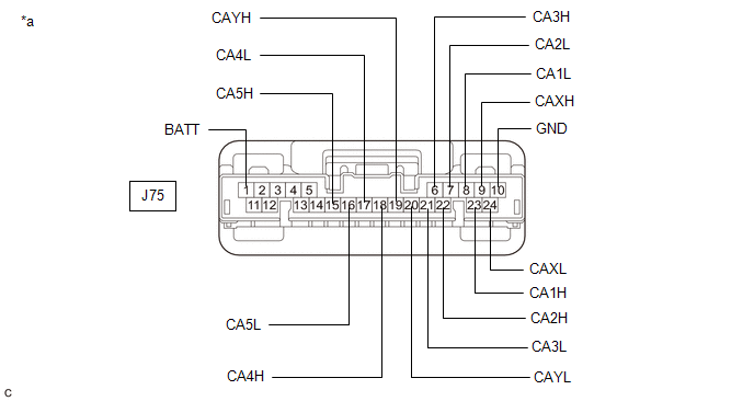
| *a | Front view of wire harness connector (to Network Gateway ECU) | - | - |
Standard Resistance:
Bus 1 Main Lines| Terminal No. (Symbol) | Wiring Color | Terminal Description | Condition | Specified Condition |
|---|---|---|---|---|
| J75-23 (CA1H) - J75-9 (CAXH) | BE - GR | HIGH-level CAN bus line - HIGH-level CAN bus line | Cable disconnected from negative (-) battery terminal | Below 1 Ω |
| J75-8 (CA1L) - J75-24 (CAXL) | LG - W | LOW-level CAN bus line - LOW-level CAN bus line | Cable disconnected from negative (-) battery terminal | Below 1 Ω |
| J75-23 (CA1H) - J75-10 (GND) | BE - W-B | HIGH-level CAN bus line - Ground | Cable disconnected from negative (-) battery terminal | 200 Ω or higher |
| J75-8 (CA1L) - J75-10 (GND) | LG - W-B | LOW-level CAN bus line - Ground | Cable disconnected from negative (-) battery terminal | 200 Ω or higher |
| J75-23 (CA1H) - J75-1 (BATT) | BE - G | HIGH-level CAN bus line - Battery positive (+) | Cable disconnected from negative (-) battery terminal | 6 kΩ or higher |
| J75-8 (CA1L) - J75-1 (BATT) | LG - G | LOW-level CAN bus line - Battery positive (+) | Cable disconnected from negative (-) battery terminal | 6 kΩ or higher |
| Terminal No. (Symbol) | Wiring Color | Terminal Description | Condition | Specified Condition |
|---|---|---|---|---|
| J75-18 (CA4H) - J75-17 (CA4L) | P - LG | HIGH-level CAN bus line - LOW-level CAN bus line | Cable disconnected from negative (-) battery terminal | 108 to 132 Ω |
| J75-18 (CA4H) - J75-10 (GND) | P - W-B | HIGH-level CAN bus line - Ground | Cable disconnected from negative (-) battery terminal | 200 Ω or higher |
| J75-17 (CA4L) - J75-10 (GND) | LG - W-B | LOW-level CAN bus line - Ground | Cable disconnected from negative (-) battery terminal | 200 Ω or higher |
| J75-18 (CA4H) - J75-1 (BATT) | P - G | HIGH-level CAN bus line - Battery positive (+) | Cable disconnected from negative (-) battery terminal | 6 kΩ or higher |
| J75-17 (CA4L) - J75-1 (BATT) | LG - G | LOW-level CAN bus line - Battery positive (+) | Cable disconnected from negative (-) battery terminal | 6 kΩ or higher |
| Terminal No. (Symbol) | Wiring Color | Terminal Description | Condition | Specified Condition |
|---|---|---|---|---|
| J75-6 (CA3H) - J75-19 (CAYH) | SB - Y | HIGH-level CAN bus line - HIGH-level CAN bus line | Cable disconnected from negative (-) battery terminal | Below 1 Ω |
| J75-21 (CA3L) - J75-20 (CAYL) | W - W | LOW-level CAN bus line - LOW-level CAN bus line | Cable disconnected from negative (-) battery terminal | Below 1 Ω |
| J75-6 (CA3H) - J75-10 (GND) | SB - W-B | HIGH-level CAN bus line - Ground | Cable disconnected from negative (-) battery terminal | 200 Ω or higher |
| J75-21 (CA3L) - J75-10 (GND) | W - W-B | LOW-level CAN bus line - Ground | Cable disconnected from negative (-) battery terminal | 200 Ω or higher |
| J75-6 (CA3H) - J75-1 (BATT) | SB - G | HIGH-level CAN bus line - Battery positive (+) | Cable disconnected from negative (-) battery terminal | 6 kΩ or higher |
| J75-21 (CA3L) - J75-1 (BATT) | W - G | LOW-level CAN bus line - Battery positive (+) | Cable disconnected from negative (-) battery terminal | 6 kΩ or higher |
| Terminal No. (Symbol) | Wiring Color | Terminal Description | Condition | Specified Condition |
|---|---|---|---|---|
| J75-22 (CA2H) - J75-7 (CA2L) | L - R | HIGH-level CAN bus line - LOW-level CAN bus line | Cable disconnected from negative (-) battery terminal | 108 to 132 Ω |
| J75-22 (CA2H) - J75-10 (GND) | L - W-B | HIGH-level CAN bus line - Ground | Cable disconnected from negative (-) battery terminal | 200 Ω or higher |
| J75-7 (CA2L) - J75-10 (GND) | R - W-B | LOW-level CAN bus line - Ground | Cable disconnected from negative (-) battery terminal | 200 Ω or higher |
| J75-22 (CA2H) - J75-1 (BATT) | L - G | HIGH-level CAN bus line - Battery positive (+) | Cable disconnected from negative (-) battery terminal | 6 kΩ or higher |
| J75-7 (CA2L) - J75-1 (BATT) | R - G | LOW-level CAN bus line - Battery positive (+) | Cable disconnected from negative (-) battery terminal | 6 kΩ or higher |
| Terminal No. (Symbol) | Wiring Color | Terminal Description | Condition | Specified Condition |
|---|---|---|---|---|
| J75-15 (CA5H) - J75-16 (CA5L) | B - W | HIGH-level CAN bus line - LOW-level CAN bus line | Cable disconnected from negative (-) battery terminal | 108 to 132 Ω |
| J75-15 (CA5H) - J75-10 (GND) | B - W-B | HIGH-level CAN bus line - Ground | Cable disconnected from negative (-) battery terminal | 200 Ω or higher |
| J75-16 (CA5L) - J75-10 (GND) | W - W-B | LOW-level CAN bus line - Ground | Cable disconnected from negative (-) battery terminal | 200 Ω or higher |
| J75-15 (CA5H) - J75-1 (BATT) | B - G | HIGH-level CAN bus line - Battery positive (+) | Cable disconnected from negative (-) battery terminal | 6 kΩ or higher |
| J75-16 (CA5L) - J75-1 (BATT) | W - G | LOW-level CAN bus line - Battery positive (+) | Cable disconnected from negative (-) battery terminal | 6 kΩ or higher |
STEERING SENSOR
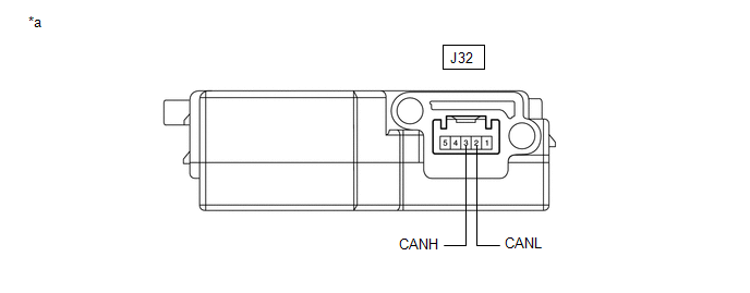
| *a | Component without harness connected (Steering Sensor) | - | - |
(a) Disconnect the cable from the negative (-) battery terminal.
(b) Disconnect the J32 steering sensor connector.
(c) Measure the resistance according to the value(s) in the table below.
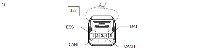
| *a | Front view of wire harness connector (to Steering Sensor) | - | - |
Standard Resistance:
| Terminal No. (Symbol) | Wiring Color | Terminal Description | Condition | Specified Condition |
|---|---|---|---|---|
| J32-3 (CANH) - J32-2 (CANL) | R - W | HIGH-level CAN bus line - LOW-level CAN bus line | Cable disconnected from negative (-) battery terminal | 54 to 69 Ω |
| J32-3 (CANH) - J32-1 (ESS) | R - W-B | HIGH-level CAN bus line - Ground | Cable disconnected from negative (-) battery terminal | 200 Ω or higher |
| J32-2 (CANL) - J32-1 (ESS) | W - W-B | LOW-level CAN bus line - Ground | Cable disconnected from negative (-) battery terminal | 200 Ω or higher |
| J32-3 (CANH) - J32-5 (BAT) | R - V | HIGH-level CAN bus line - Battery positive (+) | Cable disconnected from negative (-) battery terminal | 6 kΩ or higher |
| J32-2 (CANL) - J32-5 (BAT) | W - V | LOW-level CAN bus line - Battery positive (+) | Cable disconnected from negative (-) battery terminal | 6 kΩ or higher |
YAW RATE SENSOR ASSEMBLY (w/ TFT Meter Type Combination Meter Assembly)
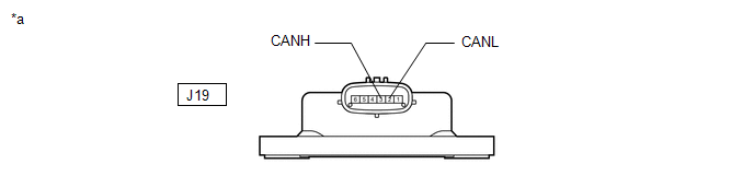
| *a | Component without harness connected (Yaw Rate Sensor Assembly) | - | - |
(a) Disconnect the cable from the negative (-) battery terminal.
(b) Disconnect the J19 yaw rate sensor assembly connector.
| *1 | DLC3 | - | - |
| *a | Front view of wire harness connector (to Yaw Rate Sensor Assembly) | - | - |
(c) Measure the resistance according to the value(s) in the table below.
Standard Resistance:
| Terminal No. (Symbol) | Wiring Color | Terminal Description | Condition | Specified Condition |
|---|---|---|---|---|
| J19-3 (CANH) - J19-2 (CANL) | P - W | HIGH-level CAN bus line - LOW-level CAN bus line | Cable disconnected from negative (-) battery terminal | 54 to 69 Ω |
| J19-3 (CANH) - J19-1 (GND) | P - W-B | HIGH-level CAN bus line - Ground | Cable disconnected from negative (-) battery terminal | 200 Ω or higher |
| J19-2 (CANL) - J19-1 (GND) | W - W-B | LOW-level CAN bus line - Ground | Cable disconnected from negative (-) battery terminal | 200 Ω or higher |
| J19-3 (CANH) - J141-16 (BAT) | P - LG | HIGH-level CAN bus line - Battery positive (+) | Cable disconnected from negative (-) battery terminal | 6 kΩ or higher |
| J19-2 (CANL) - J141-16 (BAT) | W - LG | LOW-level CAN bus line - Battery positive (+) | Cable disconnected from negative (-) battery terminal | 6 kΩ or higher |
REAR TELEVISION CAMERA ASSEMBLY
Refer to Terminals of ECU for Parking Assist Monitor System for further details.
Click here
(a) Disconnect the cable from the negative (-) battery terminal.
(b) Disconnect the Z11 rear television camera assembly connector.
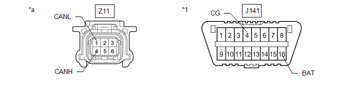
| *1 | DLC3 | - | - |
| *a | Front view of wire harness connector (to Rear Television Camera Assembly) | - | - |
(c) Measure the resistance according to the value(s) in the table below.
Standard Resistance:
| Terminal No. (Symbol) | Wiring Color | Terminal Description | Condition | Specified Condition |
|---|---|---|---|---|
| Z11-4 (CANH) - Z11-1 (CANL) | B - W | HIGH-level CAN bus line - LOW-level CAN bus line | Cable disconnected from negative (-) battery terminal | 54 to 69 Ω |
| Z11-4 (CANH) - J141-4 (CG) | B - W-B | HIGH-level CAN bus line - Ground | Cable disconnected from negative (-) battery terminal | 200 Ω or higher |
| Z11-1 (CANL) - J141-4 (CG) | W - W-B | LOW-level CAN bus line - Ground | Cable disconnected from negative (-) battery terminal | 200 Ω or higher |
| Z11-4 (CANH) - J141-16 (BAT) | B - LG | HIGH-level CAN bus line - Battery positive (+) | Cable disconnected from negative (-) battery terminal | 6 kΩ or higher |
| Z11-1 (CANL) - J141-16 (BAT) | W - LG | LOW-level CAN bus line - Battery positive (+) | Cable disconnected from negative (-) battery terminal | 6 kΩ or higher |
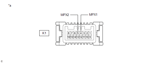
COMBINATION METER MIRROR ECU (HEADUP DISPLAY) (w/ Headup Display System)
| *a | Component without harness connected (Combination Meter Mirror ECU (Headup Display)) | - | - |
(a) Disconnect the cable from the negative (-) battery terminal.
(b) Disconnect the K1 combination meter mirror ECU (headup display) connector.
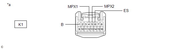
| *a | Front view of wire harness connector (to Combination Meter Mirror ECU (Headup Display)) | - | - |
(c) Measure the resistance according to the value(s) in the table below.
Standard Resistance:
| Terminal No. (Symbol) | Wiring Color | Terminal Description | Condition | Specified Condition |
|---|---|---|---|---|
| K1-4 (MPX1) - K1-5 (MPX2) | B - W | HIGH-level CAN bus line - LOW-level CAN bus line | Cable disconnected from negative (-) battery terminal | 54 to 69 Ω |
| K1-4 (MPX1) - K1-6 (ES) | B - BR | HIGH-level CAN bus line - Ground | Cable disconnected from negative (-) battery terminal | 200 Ω or higher |
| K1-5 (MPX2) - K1-6 (ES) | W - BR | LOW-level CAN bus line - Ground | Cable disconnected from negative (-) battery terminal | 200 Ω or higher |
| K1-4 (MPX1) - K1-1 (B) | B - GR | HIGH-level CAN bus line - Battery positive (+) | Cable disconnected from negative (-) battery terminal | 6 kΩ or higher |
| K1-5 (MPX2) - K1-1 (B) | W - GR | LOW-level CAN bus line - Battery positive (+) | Cable disconnected from negative (-) battery terminal | 6 kΩ or higher |
BLIND SPOT MONITOR SENSOR LH (w/ Blind Spot Monitor System)
Refer to Terminals of ECU for Blind Spot Monitor System for further details.
Click here
(a) Disconnect the cable from the negative (-) battery terminal.
(b) Disconnect the X2 blind spot monitor sensor LH connector.
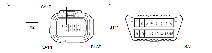
| *1 | DLC3 | - | - |
| *a | Front view of wire harness connector (to Blind Spot Monitor Sensor LH) | - | - |
(c) Measure the resistance according to the value(s) in the table below.
Standard Resistance:
| Terminal No. (Symbol) | Wiring Color | Terminal Description | Condition | Specified Condition |
|---|---|---|---|---|
| X2-2 (CA1P) - X2-7 (CA1N) | P - W | HIGH-level CAN bus line - LOW-level CAN bus line | Cable disconnected from negative (-) battery terminal | 54 to 69 Ω |
| X2-2 (CA1P) - X2-10 (BLGD) | P - W-B | HIGH-level CAN bus line - Ground | Cable disconnected from negative (-) battery terminal | 200 Ω or higher |
| X2-7 (CA1N) - X2-10 (BLGD) | W - W-B | LOW-level CAN bus line - Ground | Cable disconnected from negative (-) battery terminal | 200 Ω or higher |
| X2-2 (CA1P) - J141-16 (BAT) | P - LG | HIGH-level CAN bus line - Battery positive (+) | Cable disconnected from negative (-) battery terminal | 6 kΩ or higher |
| X2-7 (CA1N) - J141-16 (BAT) | W - LG | LOW-level CAN bus line - Battery positive (+) | Cable disconnected from negative (-) battery terminal | 6 kΩ or higher |
MILLIMETER WAVE RADAR SENSOR ASSEMBLY
Refer to Terminals of ECU for Dynamic Radar Cruise Control System for further details.
Click here
(a) Disconnect the cable from the negative (-) battery terminal.
(b) Disconnect the A70 millimeter wave radar sensor assembly connector.
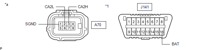
| *1 | DLC3 | - | - |
| *a | Front view of wire harness connector (to Millimeter Wave Radar Sensor Assembly) | - | - |
(c) Measure the resistance according to the value(s) in the table below.
Standard Resistance:
| Terminal No. (Symbol) | Wiring Color | Terminal Description | Condition | Specified Condition |
|---|---|---|---|---|
| A70-3 (CA2H) - A70-2 (CA2L) | BR - V | HIGH-level CAN bus line - LOW-level CAN bus line | Cable disconnected from negative (-) battery terminal | 54 to 69 Ω |
| A70-3 (CA2H) - A70-1 (SGND) | BR - W-B | HIGH-level CAN bus line - Ground | Cable disconnected from negative (-) battery terminal | 200 Ω or higher |
| A70-2 (CA2L) - A70-1 (SGND) | V - W-B | LOW-level CAN bus line - Ground | Cable disconnected from negative (-) battery terminal | 200 Ω or higher |
| A70-3 (CA2H) - J141-16 (BAT) | BR - LG | HIGH-level CAN bus line - Battery positive (+) | Cable disconnected from negative (-) battery terminal | 6 kΩ or higher |
| A70-2 (CA2L) - J141-16 (BAT) | V - LG | LOW-level CAN bus line - Battery positive (+) | Cable disconnected from negative (-) battery terminal | 6 kΩ or higher |
CLEARANCE WARNING ECU ASSEMBLY (w/ Intuitive Parking Assist System)
Refer to Terminals of ECU for Intuitive Parking Assist System for further details.
Click here
(a) Disconnect the cable from the negative (-) battery terminal.
(b) Disconnect the J38 clearance warning ECU assembly connector.
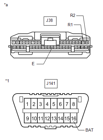
| *1 | DLC3 |
| *a | Front view of wire harness connector (to Clearance Warning ECU Assembly) |
(c) Measure the resistance according to the value(s) in the table below.
Standard Resistance:
| Terminal No. (Symbol) | Wiring Color | Terminal Description | Condition | Specified Condition |
|---|---|---|---|---|
| J38-17 (R1) - J38-18 (R2) | L - W | HIGH-level CAN bus line - LOW-level CAN bus line | Cable disconnected from negative (-) battery terminal | 54 to 69 Ω |
| J38-17 (R1) - J38-30 (E) | L - W-B | HIGH-level CAN bus line - Ground | Cable disconnected from negative (-) battery terminal | 200 Ω or higher |
| J38-18 (R2) - J38-30 (E) | W - W-B | LOW-level CAN bus line - Ground | Cable disconnected from negative (-) battery terminal | 200 Ω or higher |
| J38-17 (R1) - J141-16 (BAT) | L - LG | HIGH-level CAN bus line - Battery positive (+) | Cable disconnected from negative (-) battery terminal | 6 kΩ or higher |
| J38-18 (R2) - J141-16 (BAT) | W - LG | LOW-level CAN bus line - Battery positive (+) | Cable disconnected from negative (-) battery terminal | 6 kΩ or higher |
FORWARD RECOGNITION CAMERA
Refer to Terminals of ECU for LKA/LDA System for further details.
Click here
(a) Disconnect the cable from the negative (-) battery terminal.
(b) Disconnect the U14 forward recognition camera connector.
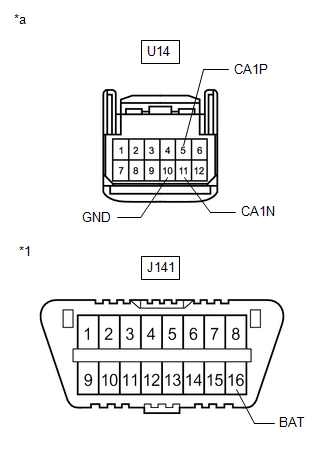
| *1 | DLC3 |
| *a | Front view of wire harness connector (to Forward Recognition Camera) |
(c) Measure the resistance according to the value(s) in the table below.
Standard Resistance:
| Terminal No. (Symbol) | Wiring Color | Terminal Description | Condition | Specified Condition |
|---|---|---|---|---|
| U14-5 (CA1P) - U14-11 (CA1N) | V - P | HIGH-level CAN bus line - LOW-level CAN bus line | Cable disconnected from negative (-) battery terminal | 54 to 69 Ω |
| U14-5 (CA1P) - U14-10 (GND) | V - BR | HIGH-level CAN bus line - Ground | Cable disconnected from negative (-) battery terminal | 200 Ω or higher |
| U14-11 (CA1N) - U14-10 (GND) | P - BR | LOW-level CAN bus line - Ground | Cable disconnected from negative (-) battery terminal | 200 Ω or higher |
| U14-5 (CA1P) - J141-16 (BAT) | V - LG | HIGH-level CAN bus line - Battery positive (+) | Cable disconnected from negative (-) battery terminal | 6 kΩ or higher |
| U14-11 (CA1N) - J141-16 (BAT) | P - LG | LOW-level CAN bus line - Battery positive (+) | Cable disconnected from negative (-) battery terminal | 6 kΩ or higher |
PARKING ASSIST ECU (w/ Panoramic View Monitor System)
Refer to Terminals of ECU for Panoramic View Monitor System for further details.
Click here
(a) Disconnect the cable from the negative (-) battery terminal.
(b) Disconnect the J159 parking assist ECU connector.

| *a | Front view of wire harness connector (to Parking Assist ECU) |
(c) Measure the resistance according to the value(s) in the table below.
Standard Resistance:
| Terminal No. (Symbol) | Wiring Color | Terminal Description | Condition | Specified Condition |
|---|---|---|---|---|
| J159-11 (CANH) - J159-12 (CANL) | LG - W | HIGH-level CAN bus line - LOW-level CAN bus line | Cable disconnected from negative (-) battery terminal | 54 to 69 Ω |
| J159-11 (CANH) - J159-4 (GND1) | LG - LA | HIGH-level CAN bus line - Ground | Cable disconnected from negative (-) battery terminal | 200 Ω or higher |
| J159-12 (CANL) - J159-4 (GND1) | W - LA | LOW-level CAN bus line - Ground | Cable disconnected from negative (-) battery terminal | 200 Ω or higher |
| J159-11 (CANH) - J159-1 (+B) | LG - LA-L | HIGH-level CAN bus line - Battery positive (+) | Cable disconnected from negative (-) battery terminal | 6 kΩ or higher |
| J159-12 (CANL) - J159-1 (+B) | W - LA-L | LOW-level CAN bus line - Battery positive (+) | Cable disconnected from negative (-) battery terminal | 6 kΩ or higher |
ECM
Refer to Terminals of ECU for SFI System for further details.
Click here
(a) Disconnect the cable from the negative (-) battery terminal.
(b) Disconnect the A37 and D2 ECM connectors.
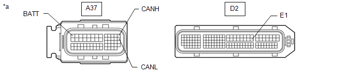
| *a | Front view of wire harness connector (to ECM) | - | - |
(c) Measure the resistance according to the value(s) in the table below.
Standard Resistance:
| Terminal No. (Symbol) | Wiring Color | Terminal Description | Condition | Specified Condition |
|---|---|---|---|---|
| A37-13 (CANH) - A37-26 (CANL) | Y - P | HIGH-level CAN bus line - LOW-level CAN bus line | Cable disconnected from negative (-) battery terminal | 108 to 132 Ω |
| A37-13 (CANH) - D2-53 (E1) | Y - BR | HIGH-level CAN bus line - Ground | Cable disconnected from negative (-) battery terminal | 200 Ω or higher |
| A37-26 (CANL) - D2-53 (E1) | P - BR | LOW-level CAN bus line - Ground | Cable disconnected from negative (-) battery terminal | 200 Ω or higher |
| A37-13 (CANH) - A37-1 (BATT) | Y - G | HIGH-level CAN bus line - Battery positive (+) | Cable disconnected from negative (-) battery terminal | 6 kΩ or higher |
| A37-26 (CANL) - A37-1 (BATT) | P - G | LOW-level CAN bus line - Battery positive (+) | Cable disconnected from negative (-) battery terminal | 6 kΩ or higher |
RADIO RECEIVER ASSEMBLY
Refer to Terminals of ECU for Audio and Visual System or Navigation System for further details.
-
Click here (for Audio and Visual System (for 8 Inch Display))
-
Click here (for Audio and Visual System (for 12.3 Inch Display))
-
Click here (for Navigation System)
(a) Disconnect the cable from the negative (-) battery terminal.
(b) Disconnect the J151 radio receiver assembly connector.
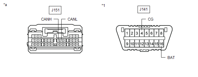
| *1 | DLC3 | - | - |
| *a | Front view of wire harness connector (to Radio Receiver Assembly) | - | - |
(c) Measure the resistance according to the value(s) in the table below.
Standard Resistance:
| Terminal No. (Symbol) | Wiring Color | Terminal Description | Condition | Specified Condition |
|---|---|---|---|---|
| J151-13 (CANH) - J151-14 (CANL) | BE - W | HIGH-level CAN bus line - LOW-level CAN bus line | Cable disconnected from negative (-) battery terminal | 54 to 69 Ω |
| J151-13 (CANH) - J141-4 (CG) | BE - W-B | HIGH-level CAN bus line - Ground | Cable disconnected from negative (-) battery terminal | 200 Ω or higher |
| J151-14 (CANL) - J141-4 (CG) | W - W-B | LOW-level CAN bus line - Ground | Cable disconnected from negative (-) battery terminal | 200 Ω or higher |
| J151-13 (CANH) - J141-16 (BAT) | BE - LG | HIGH-level CAN bus line - Battery positive (+) | Cable disconnected from negative (-) battery terminal | 6 kΩ or higher |
| J151-14 (CANL) - J141-16 (BAT) | W - LG | LOW-level CAN bus line - Battery positive (+) | Cable disconnected from negative (-) battery terminal | 6 kΩ or higher |
DCM (TELEMATICS TRANSCEIVER) (w/ Manual (SOS) Switch)
Refer to Terminals of ECU for Telematics System for further details.
Click here
(a) Disconnect the cable from the negative (-) battery terminal.
(b) Disconnect the J157 DCM (telematics transceiver) connector.
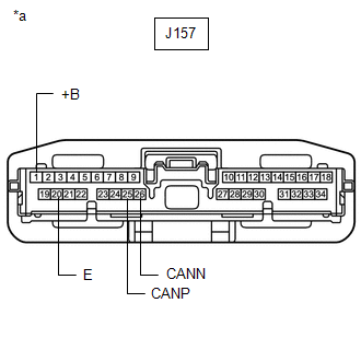
| *a | Front view of wire harness connector (to DCM (Telematics Transceiver)) |
(c) Measure the resistance according to the value(s) in the table below.
Standard Resistance:
| Terminal No. (Symbol) | Wiring Color | Terminal Description | Condition | Specified Condition |
|---|---|---|---|---|
| J157-25 (CANP) - J157-26 (CANN) | L - W | HIGH-level CAN bus line - LOW-level CAN bus line | Cable disconnected from negative (-) battery terminal | 54 to 69 Ω |
| J157-25 (CANP) - J157-20 (E) | L - W-B | HIGH-level CAN bus line - Ground | Cable disconnected from negative (-) battery terminal | 200 Ω or higher |
| J157-26 (CANN) - J157-20 (E) | W - W-B | LOW-level CAN bus line - Ground | Cable disconnected from negative (-) battery terminal | 200 Ω or higher |
| J157-25 (CANP) - J157-1 (+B) | L - Y | HIGH-level CAN bus line - Battery positive (+) | Cable disconnected from negative (-) battery terminal | 6 kΩ or higher |
| J157-26 (CANN) - J157-1 (+B) | W - Y | LOW-level CAN bus line - Battery positive (+) | Cable disconnected from negative (-) battery terminal | 6 kΩ or higher |
SKID CONTROL ECU (BRAKE ACTUATOR ASSEMBLY)
Refer to Terminals of ECU for Vehicle Stability Control System for further details.
Click here
(a) Disconnect the cable from the negative (-) battery terminal.
(b) Disconnect the A41 skid control ECU (brake actuator assembly) connector.
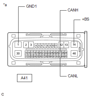
| *a | Front view of wire harness connector (to Skid Control ECU (Brake Actuator Assembly)) |
(c) Measure the resistance according to the value(s) in the table below.
Standard Resistance:
| Terminal No. (Symbol) | Wiring Color | Terminal Description | Condition | Specified Condition |
|---|---|---|---|---|
| A41-27 (CANH) - A41-43 (CANL) | B - W | HIGH-level CAN bus line - LOW-level CAN bus line | Cable disconnected from negative (-) battery terminal | 54 to 69 Ω |
| A41-27 (CANH) - A41-1 (GND1) | B - W-B | HIGH-level CAN bus line - Ground | Cable disconnected from negative (-) battery terminal | 200 Ω or higher |
| A41-43 (CANL) - A41-1 (GND1) | W - W-B | LOW-level CAN bus line - Ground | Cable disconnected from negative (-) battery terminal | 200 Ω or higher |
| A41-27 (CANH) - A41-14 (+BS) | B - L | HIGH-level CAN bus line - Battery positive (+) | Cable disconnected from negative (-) battery terminal | 6 kΩ or higher |
| A41-43 (CANL) - A41-14 (+BS) | W - L | LOW-level CAN bus line - Battery positive (+) | Cable disconnected from negative (-) battery terminal | 6 kΩ or higher |
POWER STEERING ECU ASSEMBLY
Refer to Terminals of ECU for Power Steering System for further details.
Click here
(a) Disconnect the cable from the negative (-) battery terminal.
(b) Disconnect the J4 and J5 power steering ECU assembly connectors.
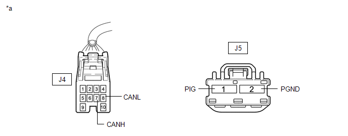
| *a | Front view of wire harness connector (to Power Steering ECU Assembly) | - | - |
(c) Measure the resistance according to the value(s) in the table below.
Standard Resistance:
| Terminal No. (Symbol) | Wiring Color | Terminal Description | Condition | Specified Condition |
|---|---|---|---|---|
| J4-7 (CANH) - J4-8 (CANL) | GR - W | HIGH-level CAN bus line - LOW-level CAN bus line | Cable disconnected from negative (-) battery terminal | 54 to 69 Ω |
| J4-7 (CANH) - J5-2 (PGND) | GR - B | HIGH-level CAN bus line - Ground | Cable disconnected from negative (-) battery terminal | 200 Ω or higher |
| J4-8 (CANL) - J5-2 (PGND) | W - B | LOW-level CAN bus line - Ground | Cable disconnected from negative (-) battery terminal | 200 Ω or higher |
| J4-7 (CANH) - J5-1 (PIG) | GR - W | HIGH-level CAN bus line - Battery positive (+) | Cable disconnected from negative (-) battery terminal | 6 kΩ or higher |
| J4-8 (CANL) - J5-1 (PIG) | W - W | LOW-level CAN bus line - Battery positive (+) | Cable disconnected from negative (-) battery terminal | 6 kΩ or higher |
AIRBAG SENSOR ASSEMBLY
Refer to Terminals of ECU for Airbag System for further details.
Click here
(a) Disconnect the cable from the negative (-) battery terminal.
(b) Disconnect the J142 airbag sensor assembly connector.
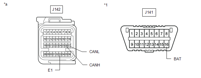
| *1 | DLC3 | - | - |
| *a | Front view of wire harness connector (to Airbag Sensor Assembly) | - | - |
(c) Measure the resistance according to the value(s) in the table below.
Standard Resistance:
| Terminal No. (Symbol) | Wiring Color | Terminal Description | Condition | Specified Condition |
|---|---|---|---|---|
| J142-26 (CANH) - J142-27 (CANL) | B - W | HIGH-level CAN bus line - LOW-level CAN bus line | Cable disconnected from negative (-) battery terminal | 108 to 132 Ω |
| J142-26 (CANH) - J142-33 (E1) | B - W-B | HIGH-level CAN bus line - Ground | Cable disconnected from negative (-) battery terminal | 200 Ω or higher |
| J142-27 (CANL) - J142-33 (E1) | W - W-B | LOW-level CAN bus line - Ground | Cable disconnected from negative (-) battery terminal | 200 Ω or higher |
| J142-26 (CANH) - J141-16 (BAT) | B - LG | HIGH-level CAN bus line - Battery positive (+) | Cable disconnected from negative (-) battery terminal | 6 kΩ or higher |
| J142-27 (CANL) - J141-16 (BAT) | W - LG | LOW-level CAN bus line - Battery positive (+) | Cable disconnected from negative (-) battery terminal | 6 kΩ or higher |
4WD ECU ASSEMBLY (for AWD)
Refer to Terminals of ECU for Dynamic Torque Control AWD System for further details.
Click here
(a) Disconnect the cable from the negative (-) battery terminal.
(b) Disconnect the R10 4WD ECU assembly connector.
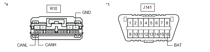
| *1 | DLC3 | - | - |
| *a | Front view of wire harness connector (to 4WD ECU Assembly) | - | - |
(c) Measure the resistance according to the value(s) in the table below.
Standard Resistance:
| Terminal No. (Symbol) | Wiring Color | Terminal Description | Condition | Specified Condition |
|---|---|---|---|---|
| R10-6 (CANH) - R10-5 (CANL) | B - W | HIGH-level CAN bus line - LOW-level CAN bus line | Cable disconnected from negative (-) battery terminal | 54 to 69 Ω |
| R10-6 (CANH) - R10-4 (GND) | B - W-B | HIGH-level CAN bus line - Ground | Cable disconnected from negative (-) battery terminal | 200 Ω or higher |
| R10-5 (CANL) - R10-4 (GND) | W - W-B | LOW-level CAN bus line - Ground | Cable disconnected from negative (-) battery terminal | 200 Ω or higher |
| R10-6 (CANH) - J141-16 (BAT) | B - LG | HIGH-level CAN bus line - Battery positive (+) | Cable disconnected from negative (-) battery terminal | 6 kΩ or higher |
| R10-5 (CANL) - J141-16 (BAT) | W - LG | LOW-level CAN bus line - Battery positive (+) | Cable disconnected from negative (-) battery terminal | 6 kΩ or higher |
TIRE PRESSURE WARNING ECU AND RECEIVER
Refer to Terminals of ECU for Tire Pressure Warning System for further details.
Click here
(a) Disconnect the cable from the negative (-) battery terminal.
(b) Disconnect the R23 tire pressure warning ECU and receiver connector.
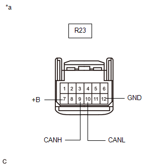
| *a | Front view of wire harness connector (to Tire Pressure Warning ECU and Receiver) |
(c) Measure the resistance according to the value(s) in the table below.
Standard Resistance:
| Terminal No. (Symbol) | Wiring Color | Terminal Description | Condition | Specified Condition |
|---|---|---|---|---|
| R23-9 (CANH) - R23-10 (CANL) | R - W | HIGH-level CAN bus line - LOW-level CAN bus line | Cable disconnected from negative (-) battery terminal | 54 to 69 Ω |
| R23-9 (CANH) - R23-12 (GND) | R - W-B | HIGH-level CAN bus line - Ground | Cable disconnected from negative (-) battery terminal | 200 Ω or higher |
| R23-10 (CANL) - R23-12 (GND) | W - W-B | LOW-level CAN bus line - Ground | Cable disconnected from negative (-) battery terminal | 200 Ω or higher |
| R23-9 (CANH) - R23-7 (+B) | R - SB | HIGH-level CAN bus line - Battery positive (+) | Cable disconnected from negative (-) battery terminal | 6 kΩ or higher |
| R23-10 (CANL) - R23-7 (+B) | W - SB | LOW-level CAN bus line - Battery positive (+) | Cable disconnected from negative (-) battery terminal | 6 kΩ or higher |
ABSORBER CONTROL ECU (w/ AVS)
Refer to Terminals of ECU for Adaptive Variable Suspension System for further details.
Click here
(a) Disconnect the cable from the negative (-) battery terminal.
(b) Disconnect the S51 absorber control ECU connector.
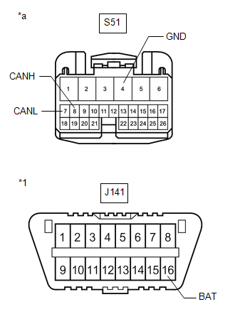
| *1 | DLC3 |
| *a | Front view of wire harness connector (to Absorber Control ECU) |
(c) Measure the resistance according to the value(s) in the table below.
Standard Resistance:
| Terminal No. (Symbol) | Wiring Color | Terminal Description | Condition | Specified Condition |
|---|---|---|---|---|
| S51-8 (CANH) - S51-7 (CANL) | R - W | HIGH-level CAN bus line - LOW-level CAN bus line | Cable disconnected from negative (-) battery terminal | 54 to 69 Ω |
| S51-8 (CANH) - S51-4 (GND) | R - W-B | HIGH-level CAN bus line - Ground | Cable disconnected from negative (-) battery terminal | 200 Ω or higher |
| S51-7 (CANL) - S51-4 (GND) | W - W-B | LOW-level CAN bus line - Ground | Cable disconnected from negative (-) battery terminal | 200 Ω or higher |
| S51-8 (CANH) - J141-16 (BAT) | R - LG | HIGH-level CAN bus line - Battery positive (+) | Cable disconnected from negative (-) battery terminal | 6 kΩ or higher |
| S51-7 (CANL) - J141-16 (BAT) | W - LG | LOW-level CAN bus line - Battery positive (+) | Cable disconnected from negative (-) battery terminal | 6 kΩ or higher |
COMBINATION METER ASSEMBLY
Refer to Terminals of ECU for Meter / Gauge System for further details.
Click here
(a) Disconnect the cable from the negative (-) battery terminal.
(b) Disconnect the J10 combination meter assembly connector.
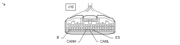
| *a | Front view of wire harness connector (to Combination Meter Assembly) | - | - |
(c) Measure the resistance according to the value(s) in the table below.
Standard Resistance:
| Terminal No. (Symbol) | Wiring Color | Terminal Description | Condition | Specified Condition |
|---|---|---|---|---|
| J10-29 (CANH) - J10-30 (CANL) | GR - W | HIGH-level CAN bus line - LOW-level CAN bus line | Cable disconnected from negative (-) battery terminal | 108 to 132 Ω |
| J10-29 (CANH) - J10-31 (ES) | GR - W-B | HIGH-level CAN bus line - Ground | Cable disconnected from negative (-) battery terminal | 200 Ω or higher |
| J10-30 (CANL) - J10-31 (ES) | W - W-B | LOW-level CAN bus line - Ground | Cable disconnected from negative (-) battery terminal | 200 Ω or higher |
| J10-29 (CANH) - J10-22 (B) | GR - G | HIGH-level CAN bus line - Battery positive (+) | Cable disconnected from negative (-) battery terminal | 6 kΩ or higher |
| J10-30 (CANL) - J10-22 (B) | W - G | LOW-level CAN bus line - Battery positive (+) | Cable disconnected from negative (-) battery terminal | 6 kΩ or higher |
MAIN BODY ECU (MULTIPLEX NETWORK BODY ECU)
Refer to Terminals of ECU for Lighting System (w/ Automatic Headlight Beam Level Control System) for further details.
Click here
(a) Disconnect the cable from the negative (-) battery terminal.
(b) Disconnect the J8 and J9 main body ECU (multiplex network body ECU) connectors.
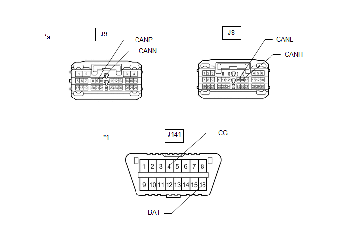
| *1 | DLC3 | - | - |
| *a | Front view of wire harness connector (to Main Body ECU (Multiplex Network Body ECU)) | - | - |
(c) Measure the resistance according to the value(s) in the table below.
Standard Resistance:
Bus 5 Branch Lines| Terminal No. (Symbol) | Wiring Color | Terminal Description | Condition | Specified Condition |
|---|---|---|---|---|
| J8-14 (CANH) - J8-13 (CANL) | L - W | HIGH-level CAN bus line - LOW-level CAN bus line | Cable disconnected from negative (-) battery terminal | 54 to 69 Ω |
| J8-14 (CANH) - J141-4 (CG) | L - W-B | HIGH-level CAN bus line - Ground | Cable disconnected from negative (-) battery terminal | 200 Ω or higher |
| J8-13 (CANL) - J141-4 (CG) | W - W-B | LOW-level CAN bus line - Ground | Cable disconnected from negative (-) battery terminal | 200 Ω or higher |
| J8-14 (CANH) - J141-16 (BAT) | L - LG | HIGH-level CAN bus line - Battery positive (+) | Cable disconnected from negative (-) battery terminal | 6 kΩ or higher |
| J8-13 (CANL) - J141-16 (BAT) | W - LG | LOW-level CAN bus line - Battery positive (+) | Cable disconnected from negative (-) battery terminal | 6 kΩ or higher |
| Terminal No. (Symbol) | Wiring Color | Terminal Description | Condition | Specified Condition |
|---|---|---|---|---|
| J9-9 (CANP) - J9-10 (CANN) | R - B | HIGH-level CAN bus line - LOW-level CAN bus line | Cable disconnected from negative (-) battery terminal | 108 to 132 Ω |
| J9-9 (CANP) - J141-4 (CG) | R - W-B | HIGH-level CAN bus line - Ground | Cable disconnected from negative (-) battery terminal | 200 Ω or higher |
| J9-10 (CANN) - J141-4 (CG) | B - W-B | LOW-level CAN bus line - Ground | Cable disconnected from negative (-) battery terminal | 200 Ω or higher |
| J9-9 (CANP) - J141-16 (BAT) | R - LG | HIGH-level CAN bus line - Battery positive (+) | Cable disconnected from negative (-) battery terminal | 6 kΩ or higher |
| J9-10 (CANN) - J141-16 (BAT) | B - LG | LOW-level CAN bus line - Battery positive (+) | Cable disconnected from negative (-) battery terminal | 6 kΩ or higher |
CERTIFICATION ECU (SMART KEY ECU ASSEMBLY)
Refer to Terminals of ECU for Smart Access System with Push-button Start (for Start Function) for further details.
Click here
(a) Disconnect the cable from the negative (-) battery terminal.
(b) Disconnect the J41 certification ECU (smart key ECU assembly) connector.
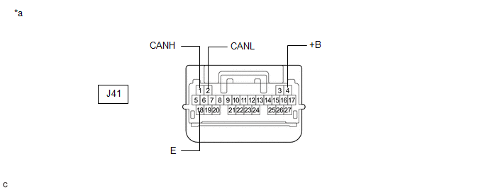
| *a | Front view of wire harness connector (to Certification ECU (Smart Key ECU Assembly)) | - | - |
(c) Measure the resistance according to the value(s) in the table below.
Standard Resistance:
| Terminal No. (Symbol) | Wiring Color | Terminal Description | Condition | Specified Condition |
|---|---|---|---|---|
| J41-1 (CANH) - J41-2 (CANL) | P - W | HIGH-level CAN bus line - LOW-level CAN bus line | Cable disconnected from negative (-) battery terminal | 54 to 69 Ω |
| J41-1 (CANH) - J41-18 (E) | P - W-B | HIGH-level CAN bus line - Ground | Cable disconnected from negative (-) battery terminal | 200 Ω or higher |
| J41-2 (CANL) - J41-18 (E) | W - W-B | LOW-level CAN bus line - Ground | Cable disconnected from negative (-) battery terminal | 200 Ω or higher |
| J41-1 (CANH) - J41-4 (+B) | P - V | HIGH-level CAN bus line - Battery positive (+) | Cable disconnected from negative (-) battery terminal | 6 kΩ or higher |
| J41-2 (CANL) - J41-4 (+B) | W - V | LOW-level CAN bus line - Battery positive (+) | Cable disconnected from negative (-) battery terminal | 6 kΩ or higher |
AIR CONDITIONING AMPLIFIER ASSEMBLY
Refer to Terminals of ECU for Air Conditioning System for further details.
Click here
(a) Disconnect the cable from the negative (-) battery terminal.
(b) Disconnect the J43 air conditioning amplifier assembly connector.
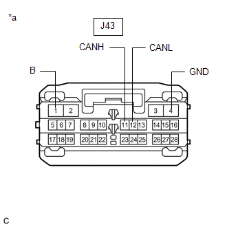
| *a | Front view of wire harness connector (to Air Conditioning Amplifier Assembly) |
(c) Measure the resistance according to the value(s) in the table below.
Standard Resistance:
| Terminal No. (Symbol) | Wiring Color | Terminal Description | Condition | Specified Condition |
|---|---|---|---|---|
| J43-11 (CANH) - J43-12 (CANL) | LG - W | HIGH-level CAN bus line - LOW-level CAN bus line | Cable disconnected from negative (-) battery terminal | 54 to 69 Ω |
| J43-11 (CANH) - J43-4 (GND) | LG - W-B | HIGH-level CAN bus line - Ground | Cable disconnected from negative (-) battery terminal | 200 Ω or higher |
| J43-12 (CANL) - J43-4 (GND) | W - W-B | LOW-level CAN bus line - Ground | Cable disconnected from negative (-) battery terminal | 200 Ω or higher |
| J43-11 (CANH) - J43-1 (B) | LG - R | HIGH-level CAN bus line - Battery positive (+) | Cable disconnected from negative (-) battery terminal | 6 kΩ or higher |
| J43-12 (CANL) - J43-1 (B) | W - R | LOW-level CAN bus line - Battery positive (+) | Cable disconnected from negative (-) battery terminal | 6 kΩ or higher |
HEADLIGHT ECU SUB-ASSEMBLY LH
Refer to Terminals of ECU for Lighting System (w/ Automatic Headlight Beam Level Control System) for further details.
Click here
(a) Disconnect the cable from the negative (-) battery terminal.
(b) Disconnect the A49 headlight ECU sub-assembly LH connector.

| *1 | DLC3 | - | - |
| *a | Front view of wire harness connector (to Headlight ECU Sub-assembly LH) | - | - |
(c) Measure the resistance according to the value(s) in the table below.
Standard Resistance:
| Terminal No. (Symbol) | Wiring Color | Terminal Description | Condition | Specified Condition |
|---|---|---|---|---|
| A49-24 (CANH) - A49-23 (CANL) | B - LG | HIGH-level CAN bus line - LOW-level CAN bus line | Cable disconnected from negative (-) battery terminal | 54 to 69 Ω |
| A49-24 (CANH) - A49-12 (GND) | B - W-B | HIGH-level CAN bus line - Ground | Cable disconnected from negative (-) battery terminal | 200 Ω or higher |
| A49-23 (CANL) - A49-12 (GND) | LG - W-B | LOW-level CAN bus line - Ground | Cable disconnected from negative (-) battery terminal | 200 Ω or higher |
| A49-24 (CANH) - J141-16 (BAT) | B - LG | HIGH-level CAN bus line - Battery positive (+) | Cable disconnected from negative (-) battery terminal | 6 kΩ or higher |
| A49-23 (CANL) - J141-16 (BAT) | LG - LG | LOW-level CAN bus line - Battery positive (+) | Cable disconnected from negative (-) battery terminal | 6 kΩ or higher |
OUTER MIRROR CONTROL ECU ASSEMBLY (for Driver Side)
Refer to Terminals of ECU for Power Mirror Control System (w/ Memory) for further details.
Click here
(a) Disconnect the cable from the negative (-) battery terminal.
(b) Disconnect the N4 outer mirror control ECU assembly (for driver side) connector.
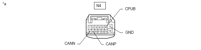
| *a | Front view of wire harness connector (to Outer Mirror Control ECU Assembly (for Driver Side)) | - | - |
(c) Measure the resistance according to the value(s) in the table below.
Standard Resistance:
| Terminal No. (Symbol) | Wiring Color | Terminal Description | Condition | Specified Condition |
|---|---|---|---|---|
| N4-9 (CANP) - N4-8 (CANN) | W - B | HIGH-level CAN bus line - LOW-level CAN bus line | Cable disconnected from negative (-) battery terminal | 54 to 69 Ω |
| N4-9 (CANP) - N4-7 (GND) | W - W-B | HIGH-level CAN bus line - Ground | Cable disconnected from negative (-) battery terminal | 200 Ω or higher |
| N4-8 (CANN) - N4-7 (GND) | B - W-B | LOW-level CAN bus line - Ground | Cable disconnected from negative (-) battery terminal | 200 Ω or higher |
| N4-9 (CANP) - N4-6 (CPUB) | W - L | HIGH-level CAN bus line - Battery positive (+) | Cable disconnected from negative (-) battery terminal | 6 kΩ or higher |
| N4-8 (CANN) - N4-6 (CPUB) | B - L | LOW-level CAN bus line - Battery positive (+) | Cable disconnected from negative (-) battery terminal | 6 kΩ or higher |
OUTER MIRROR CONTROL ECU ASSEMBLY (for Front Passenger Side)
Refer to Terminals of ECU for Power Mirror Control System (w/ Memory) for further details.
Click here
(a) Disconnect the cable from the negative (-) battery terminal.
(b) Disconnect the M4 outer mirror control ECU assembly (for front passenger side) connector.

| *a | Front view of wire harness connector (to Outer Mirror Control ECU Assembly (for Front Passenger Side)) | - | - |
(c) Measure the resistance according to the value(s) in the table below.
Standard Resistance:
| Terminal No. (Symbol) | Wiring Color | Terminal Description | Condition | Specified Condition |
|---|---|---|---|---|
| M4-9 (CANP) - M4-8 (CANN) | G - LG | HIGH-level CAN bus line - LOW-level CAN bus line | Cable disconnected from negative (-) battery terminal | 54 to 69 Ω |
| M4-9 (CANP) - M4-7 (GND) | G - W-B | HIGH-level CAN bus line - Ground | Cable disconnected from negative (-) battery terminal | 200 Ω or higher |
| M4-8 (CANN) - M4-7 (GND) | LG - W-B | LOW-level CAN bus line - Ground | Cable disconnected from negative (-) battery terminal | 200 Ω or higher |
| M4-9 (CANP) - M4-6 (CPUB) | G - GR | HIGH-level CAN bus line - Battery positive (+) | Cable disconnected from negative (-) battery terminal | 6 kΩ or higher |
| M4-8 (CANN) - M4-6 (CPUB) | LG - GR | LOW-level CAN bus line - Battery positive (+) | Cable disconnected from negative (-) battery terminal | 6 kΩ or higher |
POSITION CONTROL ECU AND SWITCH ASSEMBLY LH (w/ Seat Position Memory System)
Refer to Terminals of ECU for Front Power Seat Control System (w/ Memory) for further details.
Click here
(a) Disconnect the cable from the negative (-) battery terminal.
(b) Disconnect the c5 and c6 position control ECU and switch assembly LH connectors.
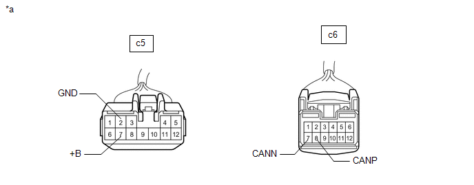
| *a | Front view of wire harness connector (to Position Control ECU and Switch Assembly LH) | - | - |
(c) Measure the resistance according to the value(s) in the table below.
Standard Resistance:
| Terminal No. (Symbol) | Wiring Color | Terminal Description | Condition | Specified Condition |
|---|---|---|---|---|
|
*1: w/ Seat Variable Cushion Switch
*2: w/o Seat Variable Cushion Switch | ||||
| c6-8 (CANP) - c6-7 (CANN) | L - W | HIGH-level CAN bus line - LOW-level CAN bus line | Cable disconnected from negative (-) battery terminal | 54 to 69 Ω |
| c6-8 (CANP) - c5-2 (GND) | L - W-B | HIGH-level CAN bus line - Ground | Cable disconnected from negative (-) battery terminal | 200 Ω or higher |
| c6-7 (CANN) - c5-2 (GND) | W - W-B | LOW-level CAN bus line - Ground | Cable disconnected from negative (-) battery terminal | 200 Ω or higher |
| c6-8 (CANP) - c5-7 (+B) | L - R*1 L - W*2 | HIGH-level CAN bus line - Battery positive (+) | Cable disconnected from negative (-) battery terminal | 6 kΩ or higher |
| c6-7 (CANN) - c5-7 (+B) | W - R*1 W - W*2 | LOW-level CAN bus line - Battery positive (+) | Cable disconnected from negative (-) battery terminal | 6 kΩ or higher |
MULTIPLEX NETWORK DOOR ECU
Refer to Terminals of ECU for Power Back Door System for further details.
Click here
(a) Disconnect the cable from the negative (-) battery terminal.
(b) Disconnect the Z16 and Z17 multiplex network door ECU connectors.
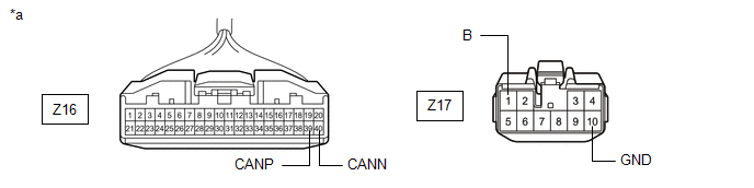
| *a | Front view of wire harness connector (to Multiplex Network Door ECU) | - | - |
(c) Measure the resistance according to the value(s) in the table below.
Standard Resistance:
| Terminal No. (Symbol) | Wiring Color | Terminal Description | Condition | Specified Condition |
|---|---|---|---|---|
| Z16-39 (CANP) - Z16-40 (CANN) | W - B | HIGH-level CAN bus line - LOW-level CAN bus line | Cable disconnected from negative (-) battery terminal | 54 to 69 Ω |
| Z16-39 (CANP) - Z17-10 (GND) | W - W-B | HIGH-level CAN bus line - Ground | Cable disconnected from negative (-) battery terminal | 200 Ω or higher |
| Z16-40 (CANN) - Z17-10 (GND) | B - W-B | LOW-level CAN bus line - Ground | Cable disconnected from negative (-) battery terminal | 200 Ω or higher |
| Z16-39 (CANP) - Z17-1 (B) | W - Y | HIGH-level CAN bus line - Battery positive (+) | Cable disconnected from negative (-) battery terminal | 6 kΩ or higher |
| Z16-40 (CANN) - Z17-1 (B) | B - Y | LOW-level CAN bus line - Battery positive (+) | Cable disconnected from negative (-) battery terminal | 6 kΩ or higher |
MULTIPLEX TILT AND TELESCOPIC ECU
Refer to Terminals of ECU for Power Tilt and Power Telescopic Steering Column System for further details.
Click here
(a) Disconnect the cable from the negative (-) battery terminal.
(b) Disconnect the J25 multiplex tilt and telescopic ECU connector.
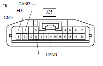
| *a | Front view of wire harness connector (to Multiplex Tilt and Telescopic ECU) |
(c) Measure the resistance according to the value(s) in the table below.
Standard Resistance:
| Terminal No. (Symbol) | Wiring Color | Terminal Description | Condition | Specified Condition |
|---|---|---|---|---|
| J25-3 (CANP) - J25-11 (CANN) | L - GR | HIGH-level CAN bus line - LOW-level CAN bus line | Cable disconnected from negative (-) battery terminal | 54 to 69 Ω |
| J25-3 (CANP) - J25-1 (GND) | L - W-B | HIGH-level CAN bus line - Ground | Cable disconnected from negative (-) battery terminal | 200 Ω or higher |
| J25-11 (CANN) - J25-1 (GND) | GR - W-B | LOW-level CAN bus line - Ground | Cable disconnected from negative (-) battery terminal | 200 Ω or higher |
| J25-3 (CANP) - J25-2 (+B) | L - R | HIGH-level CAN bus line - Battery positive (+) | Cable disconnected from negative (-) battery terminal | 6 kΩ or higher |
| J25-11 (CANN) - J25-2 (+B) | GR - R | LOW-level CAN bus line - Battery positive (+) | Cable disconnected from negative (-) battery terminal | 6 kΩ or higher |
OCCUPANT DETECTION ECU
Refer to Terminals of ECU for Occupant Classification System for further details.
Click here
(a) Disconnect the cable from the negative (-) battery terminal.
(b) Disconnect the A occupant detection ECU connector.
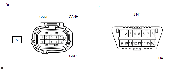
| *1 | DLC3 | - | - |
| *a | Front view of wire harness connector (to Occupant Detection ECU) | - | - |
(c) Measure the resistance according to the value(s) in the table below.
Standard Resistance:
| Terminal No. (Symbol) | Terminal Description | Condition | Specified Condition |
|---|---|---|---|
| A-5 (CANH) - A-4 (CANL) | HIGH-level CAN bus line - LOW-level CAN bus line | Cable disconnected from negative (-) battery terminal | 54 to 69 Ω |
| A-5 (CANH) - A-10 (GND) | HIGH-level CAN bus line - Ground | Cable disconnected from negative (-) battery terminal | 200 Ω or higher |
| A-4 (CANL) - A-10 (GND) | LOW-level CAN bus line - Ground | Cable disconnected from negative (-) battery terminal | 200 Ω or higher |
| A-5 (CANH) - J141-16 (BAT) | HIGH-level CAN bus line - Battery positive (+) | Cable disconnected from negative (-) battery terminal | 6 kΩ or higher |
| A-4 (CANL) - J141-16 (BAT) | LOW-level CAN bus line - Battery positive (+) | Cable disconnected from negative (-) battery terminal | 6 kΩ or higher |
 Lost Communication with "Door Control Module B" (U0200)
DESCRIPTION DTC No. Detection Item DTC Detection Condition Trouble Area Note U0200 Lost Communication with "Door Control Module B" No communication from the outer mirror control ECU ...
 Lost Communication with "Door Control Module A" (U0199)
DESCRIPTION DTC No. Detection Item DTC Detection Condition Trouble Area Note U0199 Lost Communication with "Door Control Module A" No communication from the outer mirror control ECU ...
Other materials:
Lexus RX (RX 350L, RX450h) 2016-2026 Repair Manual > Vehicle Stability Control System: Brake System Control Module "A" System Voltage System Voltage Low (C137BA2)
DESCRIPTION If a malfunction is detected in the power supply circuit, the skid control ECU (brake actuator assembly) stores this DTC and the fail-safe function prohibits ABS operation. This DTC is stored when the +BS terminal voltage meets one of the DTC detection conditions due to a malfunction in ...
Lexus RX (RX 350L, RX450h) 2016-2026 Repair Manual > Audio And Visual System (for 12.3 Inch Display): Radio Receiver Power Source Circuit
DESCRIPTION This is the power source circuit to operate the radio receiver assembly. WIRING DIAGRAM CAUTION / NOTICE / HINT NOTICE: Inspect the fuses for circuits related to this system before performing the following procedure. PROCEDURE 1. CHECK HARNESS AND CONNECTOR (RADIO RECEIVER ASSEMBL ...
Lexus RX (RX 350L, RX450h) 2016-{YEAR} Owners Manual
- For your information
- Pictorial index
- For safety and security
- Instrument cluster
- Operation of each component
- Driving
- Lexus Display Audio system
- Interior features
- Maintenance and care
- When trouble arises
- Vehicle specifications
- For owners
Lexus RX (RX 350L, RX450h) 2016-{YEAR} Repair Manual

0.0117