
Lexus RX (RX 350L, RX450h) 2016-2026 Repair Manual: Components
COMPONENTS
ILLUSTRATION
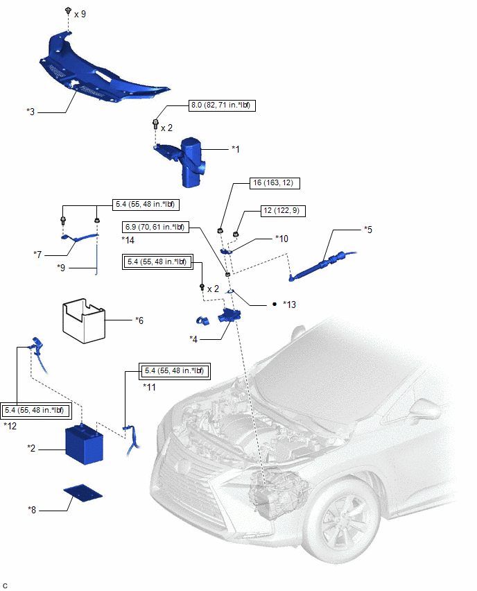
| *1 | INLET AIR CLEANER ASSEMBLY | *2 | BATTERY |
| *3 | COOL AIR INTAKE DUCT SEAL | *4 | PARK/NEUTRAL POSITION SWITCH ASSEMBLY |
| *5 | TRANSMISSION CONTROL CABLE ASSEMBLY | *6 | BATTERY INSULATOR |
| *7 | BATTERY CLAMP SUB-ASSEMBLY | *8 | BATTERY TRAY |
| *9 | BATTERY CLAMP BOLT | *10 | TRANSMISSION CONTROL SHAFT LEVER |
| *11 | NEGATIVE BATTERY TERMINAL | *12 | POSITIVE BATTERY TERMINAL |
| *13 | LOCK PLATE | *14 | LOCK NUT |
.png) | Tightening torque for "Major areas involving basic vehicle performance such as moving/turning/stopping": N*m (kgf*cm, ft.*lbf) | .png) | N*m (kgf*cm, ft.*lbf): Specified torque |
| ● | Non-reusable part | - | - |

 On-vehicle Inspection
ON-VEHICLE INSPECTION PROCEDURE 1. SECURE VEHICLE (a) Fully apply the parking brake and chock a wheel. CAUTION:
Make sure to apply the parking brake and chock a wheel before performing this procedu ...
Other materials:
Lexus RX (RX 350L, RX450h) 2016-2026 Repair Manual > Pre-collision System: Data List / Active Test
DATA LIST / ACTIVE TEST NOTICE: In the table below, the values listed under "Normal Condition" are reference values. Do not depend solely on these reference values when deciding whether a part is faulty or not. DATA LIST (a) Connect the Techstream to the DLC3. (b) Turn the engine switch on (IG). (c) ...
Lexus RX (RX 350L, RX450h) 2016-2026 Repair Manual > Theft Deterrent System: Parts Location
PARTS LOCATION ILLUSTRATION *A w/ Security Horn Assembly - - *1 ENGINE HOOD COURTESY SWITCH *2 HIGH PITCHED HORN ASSEMBLY *3 HORN RELAY *4 LOW PITCHED HORN ASSEMBLY *5 SECURITY HORN ASSEMBLY *6 ENGINE ROOM RELAY BLOCK AND JUNCTION BLOCK ASSEMBLY - HORN FUSE ...
Lexus RX (RX 350L, RX450h) 2016-{YEAR} Owners Manual
- For your information
- Pictorial index
- For safety and security
- Instrument cluster
- Operation of each component
- Driving
- Lexus Display Audio system
- Interior features
- Maintenance and care
- When trouble arises
- Vehicle specifications
- For owners
Lexus RX (RX 350L, RX450h) 2016-{YEAR} Repair Manual

0.0148