Lexus RX (RX 350L, RX450h) 2016-2026 Repair Manual: Removal
REMOVAL
CAUTION / NOTICE / HINT
The necessary procedures (adjustment, calibration, initialization or registration) that must be performed after parts are removed and installed, or replaced during park/neutral position switch assembly removal/installation are shown below.
Necessary Procedures After Parts Removed/Installed/Replaced| Replacement Part or Performed Procedure | Necessary Procedure | Effect/Inoperative Function when Necessary Procedure not Performed | Link |
|---|---|---|---|
|
*1: When performing learning using the Techstream.
Click here | |||
| Battery terminal is disconnected/reconnected | Memorize steering angle neutral point | Lane Control System | |
| Pre-collision System | |||
| Intelligent Clearance Sonar System*1 | |||
| Lighting System (w/ Automatic Headlight Beam Level Control System) | | ||
| Parking Assist Monitor System | | ||
| Panoramic View Monitor System | | ||
| Initialize back door lock | Power Door Lock Control System | | |
| Reset back door close position | Power Back Door System (w/ Outside Door Control Switch) | | |
PROCEDURE
1. PRECAUTION
NOTICE:
After turning the engine switch off, waiting time may be required before disconnecting the cable from the negative (-) battery terminal. Therefore, make sure to read the disconnecting the cable from the negative (-) battery terminal notices before proceeding with work.
Click here .gif)
2. SECURE VEHICLE
(a) Fully apply the parking brake and chock a wheel.
CAUTION:
- Make sure to apply the parking brake and chock a wheel before performing this procedure.
- If the vehicle is not secure and the shift lever is moved to N, the vehicle may suddenly move, possibly resulting in an accident or serious injury.
.png)
3. REMOVE COOL AIR INTAKE DUCT SEAL
Click here
4. REMOVE INLET AIR CLEANER ASSEMBLY
Click here
5. DISCONNECT CABLE FROM NEGATIVE BATTERY TERMINAL
NOTICE:
When disconnecting the cable, some systems need to be initialized after the cable is reconnected.
Click here
6. REMOVE BATTERY
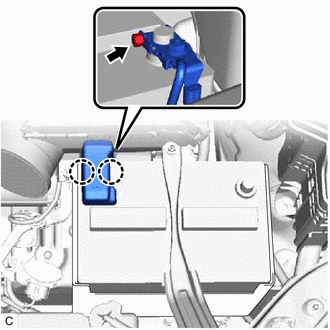
| (a) Disengage the 2 claws to open the battery terminal cap. |
|
(b) Loosen the nut and disconnect the cable from the positive (+) battery terminal.
| (c) Remove the bolt, nut and battery clamp sub-assembly. |
|
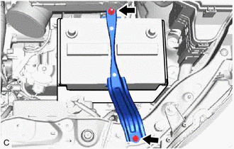
(d) Remove the battery insulator.
(e) Remove the battery and battery tray.
| (f) Remove the battery clamp bolt from the battery carrier sub-assembly. |
|
7. DISCONNECT TRANSMISSION CONTROL CABLE ASSEMBLY
(a) Move the shift lever to N.
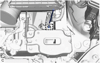
| (b) Remove the nut and disconnect the transmission control cable assembly from the transmission control shaft lever. |
|
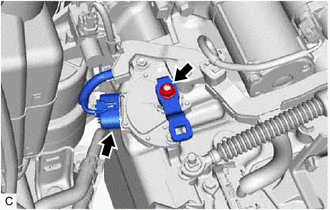
8. REMOVE PARK/NEUTRAL POSITION SWITCH ASSEMBLY
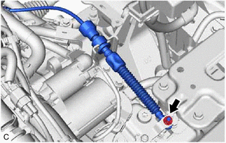
| (a) Disconnect the park/neutral position switch assembly connector. |
|
(b) Remove the nut and transmission control shaft lever from the manual valve lever shaft sub-assembly.
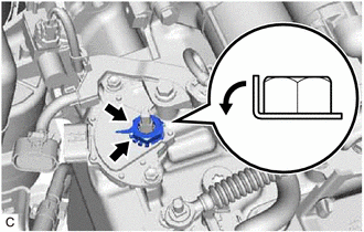
| (c) Using a screwdriver, bend back the tabs of the lock plate and remove the lock nut and lock plate from the park/neutral position switch assembly. |
|
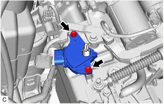
| (d) Remove the 2 bolts and park/neutral position switch assembly from the automatic transaxle case sub-assembly. NOTICE: Before removing the park/neutral position switch assembly, remove any dirt or rust on the installation portion of the manual valve lever shaft sub-assembly. Be sure to remove the park/neutral position switch assembly straight along the manual valve lever shaft sub-assembly while being careful not to deform the plate spring that supports the manual valve lever shaft sub-assembly. If the plate spring is deformed, the park/neutral position switch assembly cannot be reinstalled correctly. |
|
 On-vehicle Inspection
ON-VEHICLE INSPECTION PROCEDURE 1. SECURE VEHICLE (a) Fully apply the parking brake and chock a wheel. CAUTION:
Make sure to apply the parking brake and chock a wheel before performing this procedu ...
 Inspection
INSPECTION PROCEDURE 1. INSPECT PARK/NEUTRAL POSITION SWITCH ASSEMBLY (a) Measure the resistance according to the value(s) in the table below when the transmission control shaft lever is moved to e ...
Other materials:
Lexus RX (RX 350L, RX450h) 2016-2026 Repair Manual > Instrument Panel Safety Pad: Components
COMPONENTS ILLUSTRATION *1 COMBINATION METER ASSEMBLY *2 COWL SIDE TRIM BOARD LH *3 FRONT DOOR SCUFF PLATE LH *4 HOOD LOCK CONTROL LEVER SUB-ASSEMBLY *5 INSTRUMENT CLUSTER FINISH PANEL SUB-ASSEMBLY *6 INSTRUMENT PANEL GARNISH LH *7 LOWER INSTRUMENT FINISH PANEL SU ...
Lexus RX (RX 350L, RX450h) 2016-2026 Repair Manual > Emission Control System: On-vehicle Inspection
ON-VEHICLE INSPECTION CAUTION / NOTICE / HINT CAUTION: To prevent injury due to contact with an operating V-ribbed belt or cooling fan, keep your hands and clothing away from the V-ribbed belt and cooling fans when working in the engine compartment with the engine running or the engine switch on (IG ...
Lexus RX (RX 350L, RX450h) 2016-{YEAR} Owners Manual
- For your information
- Pictorial index
- For safety and security
- Instrument cluster
- Operation of each component
- Driving
- Lexus Display Audio system
- Interior features
- Maintenance and care
- When trouble arises
- Vehicle specifications
- For owners
Lexus RX (RX 350L, RX450h) 2016-{YEAR} Repair Manual

0.0111