Lexus RX (RX 350L, RX450h) 2016-2026 Repair Manual: Installation
INSTALLATION
PROCEDURE
1. INSTALL TRANSMISSION VALVE BODY ASSEMBLY
| (a) Connect the manual valve connecting rod to the manual valve lever sub-assembly. |
|
.png)
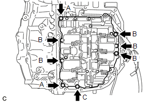
| (b) Install the transmission valve body assembly to the automatic transaxle case sub-assembly with the 8 bolts. Torque: 10 N·m {102 kgf·cm, 7 ft·lbf} Bolt Length
|
|
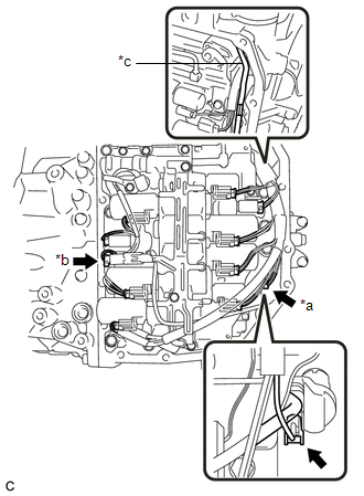
(c) Engage the clamp and guide to connect the transmission revolution sensor (NC) wire.
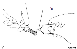
(d) Coat the O-ring of the temperature sensor with ATF.
(e) Connect the temperature sensor and install the temperature sensor clamp to the transmission valve body assembly with the bolt.
Torque:
7.0 N·m {71 kgf·cm, 62 in·lbf}
(f) Connect the 9 shift solenoid valve connectors.
| (g) Connect the transmission revolution sensor (NT) connector and transmission revolution sensor (NC) connector. NOTICE: Be sure to bend the wire harness toward the automatic transaxle case sub-assembly. If the wire harness is positioned close to the transmission valve body assembly, it may interfere with the manual valve connecting rod. |
|
2. INSTALL TRANSAXLE SIDE COVER SUB-ASSEMBLY
(a) Remove any remaining seal packing from the sealing surface of the automatic transaxle case sub-assembly.
NOTICE:
Make sure that there is no ATF on the sealing surface.
(b) Clean the 13 bolts and bolt holes in the automatic transaxle case sub-assembly.
| (c) Temporarily install 2 stud bolts to the automatic transaxle case sub-assembly by hand, to the positions shown in the illustration.
|
|
.png)
| (d) Apply FIPG to a new transaxle side cover sub-assembly. FIPG: Toyota Genuine Seal Packing 1281 Three Bond 1281 or equivalent NOTICE:
|
|
.png)
| (e) Apply adhesive to 2 or 3 threads on the ends of the 13 bolts. Adhesive: Toyota Genuine Adhesive 1344, Three Bond 1344 or equivalent NOTICE: Make sure to install the bolts immediately after applying adhesive to prevent foreign matter from attaching to them. |
|
| (f) Using a T40 "TORX" socket wrench, install the transaxle side cover sub-assembly to the automatic transaxle case sub-assembly with the 11 bolts. Torque: 13 N·m {133 kgf·cm, 10 ft·lbf} |
|
.png)
(g) Remove the 2 stud bolts.
| (h) Using a T40 "TORX" socket wrench, install the 2 bolts. Torque: 13 N·m {133 kgf·cm, 10 ft·lbf} |
|
.png)
3. INSTALL INLET NO. 1 OIL COOLER TUBE SUB-ASSEMBLY
(a) Coat a new O-ring with ATF and install it to the inlet No. 1 oil cooler tube sub-assembly.
NOTICE:
Ensure that the O-ring is not twisted.
(b) Install the inlet No. 1 oil cooler tube sub-assembly to the transaxle housing.
NOTICE:
The installation bolts will be installed after installing the outlet No. 1 oil cooler tube sub-assembly.
4. INSTALL OUTLET NO. 1 OIL COOLER TUBE SUB-ASSEMBLY
(a) Coat a new O-ring with ATF and install it to the outlet No. 1 oil cooler tube sub-assembly.
NOTICE:
Ensure that the O-ring is not twisted.
(b) Install the outlet No. 1 oil cooler tube sub-assembly to the transaxle housing.
| (c) Temporarily install the 4 bolts in the order shown in the illustration. |
|
.png)
(d) Fully tighten the 4 bolts in the order shown in the illustration.
Torque:
25 N·m {255 kgf·cm, 18 ft·lbf}
5. CONNECT NO. 1 TRANSMISSION OIL COOLER HOSE ASSEMBLY
(a) Connect the 2 No. 1 transmission oil cooler hose assemblies and slide the 2 clips to secure them.
6. INSTALL FRONT ENGINE MOUNTING INSULATOR
Click here .gif)
7. INSTALL FRONT FRAME ASSEMBLY
Click here
8. ADJUST AUTOMATIC TRANSAXLE FLUID
Click here
9. INSTALL FRONT FENDER APRON SEAL LH
Click here
10. INSTALL NO. 3 ENGINE UNDER COVER
Click here
11. INSTALL FRONT WHEEL OPENING EXTENSION PAD LH
Click here
12. INSTALL FRONT WHEEL LH
Click here
 Inspection
INSPECTION PROCEDURE 1. INSPECT SHIFT SOLENOID VALVE S1 (a) Measure the resistance according to the value(s) in the table below. Standard Resistance: Tester Connection Condition Specified C ...
 Reassembly
REASSEMBLY PROCEDURE 1. INSTALL SHIFT SOLENOID VALVE SLT (a) Coat the shift solenoid valve SLT with ATF and install it to the transmission valve body assembly. (b) Install the straight ...
Other materials:
Lexus RX (RX 350L, RX450h) 2016-2026 Repair Manual > Valve Body Assembly: Removal
REMOVAL CAUTION / NOTICE / HINT The necessary procedures (adjustment, calibration, initialization or registration) that must be performed after parts are removed and installed, or replaced during transmission valve body assembly removal/installation are shown below. Necessary Procedures After Parts ...
Lexus RX (RX 350L, RX450h) 2016-2026 Repair Manual > U881e (automatic Transmission / Transaxle): Transmission Wire
ComponentsCOMPONENTS ILLUSTRATION *1 TRANSMISSION WIRE - - Tightening torque for "Major areas involving basic vehicle performance such as moving/turning/stopping": N*m (kgf*cm, ft.*lbf) ATF WS RemovalREMOVAL PROCEDURE 1. REMOVE TRANSMISSION VALVE BODY ASSEMBLY Click here ...
Lexus RX (RX 350L, RX450h) 2016-{YEAR} Owners Manual
- For your information
- Pictorial index
- For safety and security
- Instrument cluster
- Operation of each component
- Driving
- Lexus Display Audio system
- Interior features
- Maintenance and care
- When trouble arises
- Vehicle specifications
- For owners
Lexus RX (RX 350L, RX450h) 2016-{YEAR} Repair Manual

0.0087