Lexus RX (RX 350L, RX450h) 2016-2026 Repair Manual: Components
COMPONENTS
ILLUSTRATION
| *1 | OUTER COWL TOP PANEL SUB-ASSEMBLY | - | - |
.png) | N*m (kgf*cm, ft.*lbf): Specified torque | - | - |
ILLUSTRATION
.png)
| *A | for TMC Made | *B | for TMMC Made |
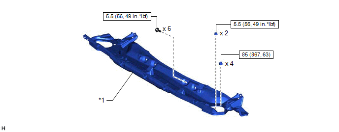
| *1 | NO. 2 ENGINE UNDER COVER | - | - |
ILLUSTRATION
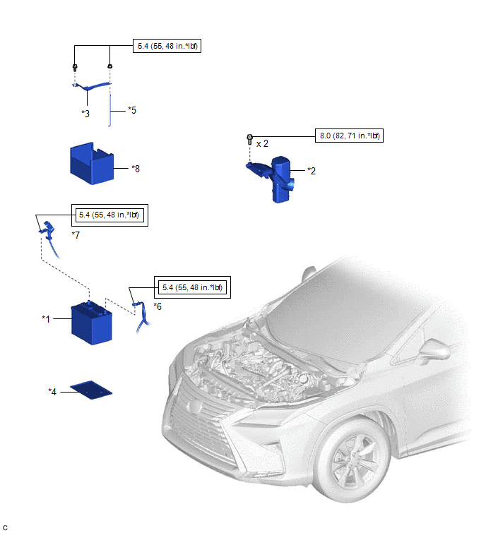
| *1 | BATTERY | *2 | INLET AIR CLEANER ASSEMBLY |
| *3 | BATTERY CLAMP SUB-ASSEMBLY | *4 | BATTERY TRAY |
| *5 | BATTERY CLAMP BOLT | *6 | BATTERY NEGATIVE TERMINAL |
| *7 | BATTERY POSITIVE TERMINAL | *8 | BATTERY INSULATOR |
.png) | Tightening torque for "Major areas involving basic vehicle performance such as moving/turning/stopping": N*m (kgf*cm, ft.*lbf) | | N*m (kgf*cm, ft.*lbf): Specified torque |
ILLUSTRATION
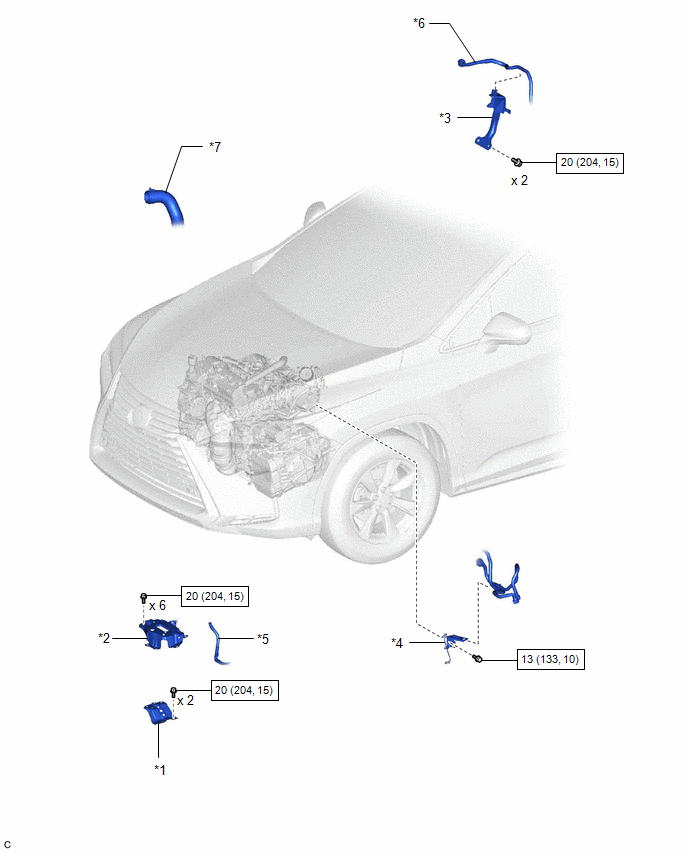
| *1 | BATTERY BRACKET REINFORCEMENT | *2 | BATTERY CARRIER SUB-ASSEMBLY |
| *3 | FUEL PUMP PROTECTOR | *4 | WIRE HARNESS CLAMP BRACKET |
| *5 | ENGINE WIRE | *6 | FUEL TUBE SUB-ASSEMBLY |
| *7 | NO. 1 RADIATOR HOSE | - | - |
| | N*m (kgf*cm, ft.*lbf): Specified torque | - | - |
ILLUSTRATION
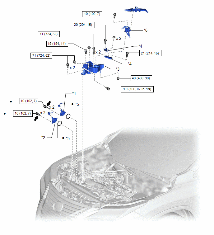
| *1 | CAMSHAFT TIMING OIL CONTROL SOLENOID ASSEMBLY (for Intake Side of Bank 2) | *2 | CAMSHAFT TIMING OIL CONTROL SOLENOID ASSEMBLY (for Exhaust Side of Bank 2) |
| *3 | ENGINE MOUNTING INSULATOR SUB-ASSEMBLY RH | *4 | NO. 2 ENGINE MOUNTING STAY RH |
| *5 | O-RING | *6 | WIRE HARNESS CLAMP BRACKET |
| | N*m (kgf*cm, ft.*lbf): Specified torque | ● | Non-reusable part |
.png) | Adhesive 1324 | ★ | Precoated part |

 On-vehicle Inspection
ON-VEHICLE INSPECTION PROCEDURE 1. INSPECT CAMSHAFT TIMING OIL CONTROL SOLENOID ASSEMBLY (a) Connect the Techstream to the DLC3. (b) Start the engine. (c) Turn the Techstream on. (d) Inspect the camsh ...
Other materials:
Lexus RX (RX 350L, RX450h) 2016-2026 Repair Manual > Telephone And Gps Antenna (for Roof Side): Installation
INSTALLATION PROCEDURE 1. INSTALL TELEPHONE AND GPS ANTENNA ASSEMBLY (a) When reusing the telephone and GPS antenna assembly: (1) Install a new seal. (b) Push the telephone and GPS antenna assembly in the direction indicated by the arrow (1) shown in the illustration to engage the guide. Inst ...
Lexus RX (RX 350L, RX450h) 2016-2026 Repair Manual > Panoramic Moon Roof System: Operation Check
OPERATION CHECK CHECK AUTO OPERATION FUNCTION (FOR SLIDING ROOF) NOTICE:
Make sure that initialization has been completed before performing this inspection.
Click here
The sliding roof auto operation function can be customized. Make sure that the auto operation function is ON.
Click here ...
Lexus RX (RX 350L, RX450h) 2016-{YEAR} Owners Manual
- For your information
- Pictorial index
- For safety and security
- Instrument cluster
- Operation of each component
- Driving
- Lexus Display Audio system
- Interior features
- Maintenance and care
- When trouble arises
- Vehicle specifications
- For owners
Lexus RX (RX 350L, RX450h) 2016-{YEAR} Repair Manual

0.0172