Lexus RX (RX 350L, RX450h) 2016-2026 Repair Manual: Removal
REMOVAL
CAUTION / NOTICE / HINT
The necessary procedures (adjustment, calibration, initialization or registration) that must be performed after parts are removed and installed, or replaced during camshaft timing gear bolt removal/installation are shown below.
Necessary Procedures After Parts Removed/Installed/Replaced| Replaced Part or Performed Procedure | Necessary Procedure | Effect/Inoperative Function when Necessary Procedure not Performed | Link |
|---|---|---|---|
| Battery terminal is disconnected/reconnected | Memorize steering angle neutral point | Lane Control System | |
| Pre-collision System | |||
| Intelligent Clearance Sonar System*1 | |||
| Parking Assist Monitor System | | ||
| Panoramic View Monitor System | | ||
| Lighting System (w/ Automatic Headlight Beam Level Control System) | | ||
| Initialize back door lock | Power Door Lock Control System | | |
| Reset back door close position | Power Back Door System (w/ Outside Door Control Switch) | | |
| Replacement of ECM | Vehicle Identification Number (VIN) registration | MIL comes on | |
| ECU Communication ID Registration (Immobiliser system) | Engine start function | | |
| Perform code registration (Immobiliser system) |
| | |
| Replacement of ECM (If possible, read the transaxle compensation code from the previous ECM) | Perform the following procedures in the order shown:
|
| |
| Replacement of ECM (If impossible, read the transaxle compensation code from the previous ECM) | Perform the following procedures in the order shown:
| ||
| Inspection After Repair |
| |
| Front wheel alignment adjustment | Calibration |
| |
| Suspension, tires, etc. (The vehicle height changes because of suspension or tire replacement) |
|
| |
| Rear television camera assembly optical axis (Back camera position setting) | Parking assist monitor system | for Initialization: for Calibration: | |
| Panoramic view monitor system | for Initialization: for Calibration: | |
| Initialize No. 1 headlight ECU sub-assembly LH | Lighting System (w/ Automatic Headlight Beam Level Control System) | |
*1: When performing learning using the Techstream.
Click here .gif)
PROCEDURE
1. REMOVE ENGINE ASSEMBLY WITH TRANSAXLE
Click here
2. REMOVE CAMSHAFT TIMING OIL CONTROL SOLENOID ASSEMBLY (for Intake Side of Bank 1)
Click here
3. REMOVE CAMSHAFT TIMING OIL CONTROL SOLENOID ASSEMBLY (for Exhaust Side of Bank 1)
Click here
4. SET NO. 1 CYLINDER TO TDC/COMPRESSION
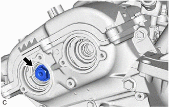
| (a) Turn the crankshaft pulley assembly clockwise until its timing mark (cutout) is aligned with the timing mark on the timing chain cover assembly as shown in the illustration. |
|
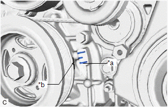
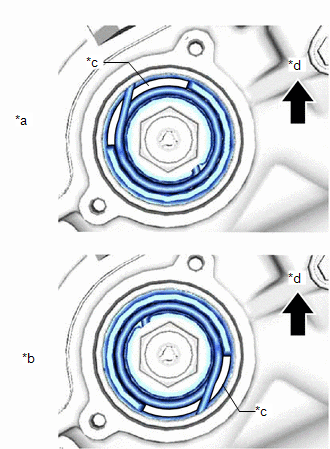
(b) Check that the cutout of the camshaft timing gear assembly is at the top.
| (1) for intake side: HINT: If the cutout of the camshaft timing gear assembly (for intake side) is not at the top, turn the crankshaft 360° clockwise and align the timing mark (cutout) of the crankshaft pulley with the timing mark on the timing chain cover assembly again. |
|
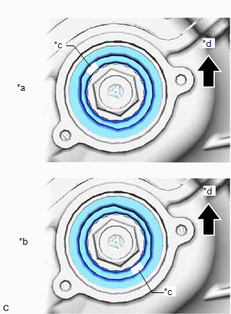
| (2) for exhaust side: HINT: If the cutout of the camshaft timing gear assembly (for exhaust side) is not at the top, turn the crankshaft 360° clockwise and align the timing mark (cutout) of the crankshaft pulley with the timing mark on the timing chain cover assembly again. |
|
5. REMOVE CAMSHAFT TIMING GEAR BOLT (for Intake Side of Bank 1)
| (a) While holding the crankshaft pulley, remove the camshaft timing gear bolt. NOTICE:
|
|
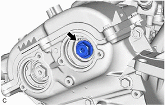
6. REMOVE CAMSHAFT TIMING GEAR BOLT (for Exhaust Side of Bank 1)
| (a) While holding the crankshaft pulley, remove the camshaft timing gear bolt. NOTICE:
|
|
 Installation
INSTALLATION CAUTION / NOTICE / HINT CAUTION:
The engine assembly with transaxle is very heavy. Be sure to follow the procedure described in the repair manual, or the engine lifter may suddenly dro ...

Other materials:
Lexus RX (RX 350L, RX450h) 2016-2026 Repair Manual > Audio And Visual System (for 8 Inch Display): Satellite Radio Broadcast cannot be Received
CAUTION / NOTICE / HINT NOTICE: Some satellite radio broadcasts require payment. A contract must be made between a satellite radio company and the user. If the contract expires, it will not be possible to listen to the broadcast. PROCEDURE 1. CHECK SURROUNDINGS (a) Check if the vehicle is i ...
Lexus RX (RX 350L, RX450h) 2016-2026 Repair Manual > Mass Air Flow Meter: Removal
REMOVAL CAUTION / NOTICE / HINT The necessary procedures (adjustment, calibration, initialization or registration) that must be performed after parts are removed and installed, or replaced during mass air flow meter sub-assembly removal/installation are shown below. Necessary Procedures After Parts ...
Lexus RX (RX 350L, RX450h) 2016-{YEAR} Owners Manual
- For your information
- Pictorial index
- For safety and security
- Instrument cluster
- Operation of each component
- Driving
- Lexus Display Audio system
- Interior features
- Maintenance and care
- When trouble arises
- Vehicle specifications
- For owners
Lexus RX (RX 350L, RX450h) 2016-{YEAR} Repair Manual

0.013