Lexus RX (RX 350L, RX450h) 2016-2026 Repair Manual: Distance Control Switch Circuit
DESCRIPTION
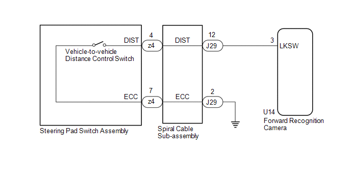
The vehicle-to-vehicle distance control switch is used to set the distance for vehicle-to-vehicle distance control mode. The vehicle-to-vehicle distance control switch is installed in the steering pad switch assembly. The vehicle-to-vehicle distance set value can be changed by operating the vehicle-to-vehicle distance control switch while the dynamic radar cruise control system is controlling vehicle speed in vehicle-to-vehicle distance control mode.
WIRING DIAGRAM
CAUTION / NOTICE / HINT
NOTICE:
-
The vehicle is equipped with a Supplemental Restraint System (SRS) which includes components such as airbags. Before servicing (including removal or installation of parts), be sure to read the precaution for Supplemental Restraint System.
Click here
.gif)
- When replacing the forward recognition camera, replace it with a new one. If a forward recognition camera which was installed to another vehicle is used, the information stored in the forward recognition camera will not match the information from the vehicle and a DTC may be stored.
-
If the forward recognition camera has been replaced with a new one, it is necessary to perform forward recognition camera adjustment.
HINT:
Forward recognition camera adjustment can be performed by using either One Time Recognition or Sequential Recognition.
One Time Recognition: Click here
Sequential Recognition: Click here
PROCEDURE
| 1. | READ VALUE USING TECHSTREAM |
(a) Connect the Techstream to the DLC3.
(b) Turn the engine switch on (IG).
(c) Turn the Techstream on.
(d) Enter the following menus: Powertrain / Radar Cruise 2 / Data List.
(e) Read the Data List according to the display on the Techstream.
Powertrain > Radar Cruise2 > Data List| Tester Display | Measurement Item | Range | Normal Condition | Diagnostic Note |
|---|---|---|---|---|
| Vehicle-to-vehicle Distance Control Switch | Vehicle-to-vehicle distance control switch signal | OFF or ON | OFF: Vehicle-to-vehicle distance control switch not pushed ON: Vehicle-to-vehicle distance control switch pushed | - |
| Tester Display |
|---|
| Vehicle-to-vehicle Distance Control Switch |
OK:
The value of the Data List item changes according to the operation of the vehicle-to-vehicle distance control switch.
| OK | .gif) | PROCEED TO NEXT SUSPECTED AREA SHOWN IN PROBLEM SYMPTOMS TABLE |
|
.gif)
| 2. | INSPECT STEERING PAD SWITCH ASSEMBLY |
(a) Remove the steering pad switch assembly.
Click here
(b) Inspect the steering pad switch assembly.
Click here
| NG | | REPLACE STEERING PAD SWITCH ASSEMBLY |
|
| 3. | INSPECT SPIRAL CABLE SUB-ASSEMBLY |
(a) Remove the spiral cable sub-assembly.
Click here
(b) Inspect the spiral cable sub-assembly.
Click here
| NG | | REPLACE SPIRAL CABLE SUB-ASSEMBLY |
|
| 4. | CHECK HARNESS AND CONNECTOR (SPIRAL CABLE SUB-ASSEMBLY - FORWARD RECOGNITION CAMERA AND BODY GROUND) |
(a) Disconnect the U14 forward recognition camera connector.
(b) Measure the resistance according to the value(s) in the table below.
Standard Resistance:
| Tester Connection | Condition | Specified Condition |
|---|---|---|
| J29-12 (DIST) - U14-3 (LKSW) | Always | Below 1 Ω |
| J29-2 (ECC) - Body ground | Always | Below 1 Ω |
| J29-12 (DIST) or U14-3 (LKSW) - Body ground | Always | 10 kΩ or higher |
| OK | | REPLACE FORWARD RECOGNITION CAMERA |
| NG | | REPAIR OR REPLACE HARNESS OR CONNECTOR |
 Cruise Control Switch Circuit
DESCRIPTION The cruise control main switch is used to turn the dynamic radar cruise control system on and off, as well as operate 7 functions: SET, - (COAST), TAP-DOWN, RES (RESUME), + (ACCEL), TAP-UP ...
 Cruise Main Indicator Light Circuit
DESCRIPTION When the dynamic radar cruise control system is turned on using the cruise control main switch, the cruise control indicator (vehicle-to-vehicle distance control mode) illuminates. The ECM ...
Other materials:
Lexus RX (RX 350L, RX450h) 2016-2026 Repair Manual > Cornering Light Assembly: Removal
REMOVAL CAUTION / NOTICE / HINT The necessary procedures (adjustment, calibration, initialization or registration) that must be performed after parts are removed and installed, or replaced during cornering light assembly (fog light assembly) removal/installation are shown below. Necessary Procedure ...
Lexus RX (RX 350L, RX450h) 2016-2026 Repair Manual > Blind Spot Monitor System: Blind Spot Monitor Slave Module (C1AB7)
DESCRIPTION This DTC is stored when the blind spot monitor sensor RH detects an internal malfunction. DTC No. Detection Item DTC Detection Condition Trouble Area C1AB7 Blind Spot Monitor Slave Module The blind spot monitor sensor RH (slave) detects an internal malfunction Blind sp ...
Lexus RX (RX 350L, RX450h) 2016-{YEAR} Owners Manual
- For your information
- Pictorial index
- For safety and security
- Instrument cluster
- Operation of each component
- Driving
- Lexus Display Audio system
- Interior features
- Maintenance and care
- When trouble arises
- Vehicle specifications
- For owners
Lexus RX (RX 350L, RX450h) 2016-{YEAR} Repair Manual

0.0101