Lexus RX (RX 350L, RX450h) 2016-2026 Repair Manual: Removal
REMOVAL
CAUTION / NOTICE / HINT
The necessary procedures (adjustment, calibration, initialization or registration) that must be performed after parts are removed and installed, or replaced during camshaft position sensor removal/installation are shown below.
Necessary Procedures After Parts Removed/Installed/Replaced| Replaced Part or Performed Procedure | Necessary Procedure | Effect/Inoperative Function when Necessary Procedure not Performed | Link |
|---|---|---|---|
| Battery terminal is disconnected/reconnected | Memorize steering angle neutral point | Lane Control System | |
| Pre-collision System | |||
| Intelligent Clearance Sonar System*1 | |||
| Parking Assist Monitor System | | ||
| Panoramic View Monitor System | | ||
| Lighting System (w/ Automatic Headlight Beam Level Control System) | | ||
| Initialize back door lock | Power Door Lock Control System | | |
| Reset back door close position | Power Back Door System (w/ Outside Door Control Switch) | | |
| Inspection After Repair |
| |
*1: When performing learning using the Techstream.
Click here .gif)
PROCEDURE
1. REMOVE INTAKE AIR SURGE TANK ASSEMBLY
Click here
2. REMOVE VVT SENSOR (for Intake Side of Bank 1)
| (a) Disconnect the VVT sensor connector. |
|
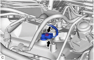
(b) Remove the bolt and VVT sensor from the cylinder head cover sub-assembly.
NOTICE:
If the VVT sensor has been struck or dropped, replace it.
3. REMOVE VVT SENSOR (for Exhaust Side of Bank 1)
| (a) Disconnect the VVT sensor connector. |
|
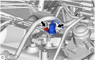
(b) Remove the bolt and VVT sensor from the cylinder head cover sub-assembly.
NOTICE:
If the VVT sensor has been struck or dropped, replace it.
4. REMOVE VVT SENSOR (for Intake Side of Bank 2)
| (a) Disconnect the VVT sensor connector. |
|
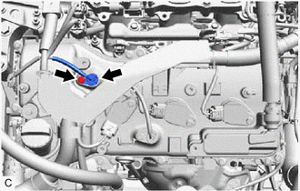
(b) Remove the bolt and VVT sensor from the cylinder head cover sub-assembly LH.
NOTICE:
If the VVT sensor has been struck or dropped, replace it.
5. REMOVE VVT SENSOR (for Exhaust Side of Bank 2)
| (a) Disconnect the VVT sensor connector. |
|
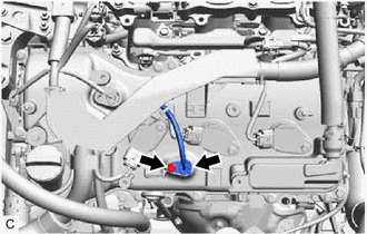
(b) Remove the bolt and VVT sensor from the cylinder head cover sub-assembly LH.
NOTICE:
If the VVT sensor has been struck or dropped, replace it.
 Components
COMPONENTS ILLUSTRATION *1 VVT SENSOR (for Intake Side of Bank 1) *2 VVT SENSOR (for Exhaust Side of Bank 1) *3 VVT SENSOR (for Intake Side of Bank 2) *4 VVT SENSOR (for Exhaust Si ...
 Installation
INSTALLATION PROCEDURE 1. INSTALL VVT SENSOR (for Exhaust Side of Bank 2) (a) Apply a light coat of engine oil to the O-ring of the VVT sensor. NOTICE: If reusing the VVT sensor, be sure to inspect th ...
Other materials:
Lexus RX (RX 350L, RX450h) 2016-2026 Repair Manual > Automatic Transaxle System: Transmission Fluid Temperature Sensor "A" Circuit Short To Ground (P071011)
DESCRIPTION The ATF temperature sensor converts the automatic transaxle fluid (ATF) temperature into a resistance value for use by the ECM. The ECM applies voltage to the temperature sensor through terminal THO1 of the ECM. The sensor resistance changes with the ATF temperature. As the temperature r ...
Lexus RX (RX 350L, RX450h) 2016-2026 Repair Manual > Front Seat Inner Belt Assembly: Inspection
INSPECTION PROCEDURE 1. INSPECT FRONT SEAT INNER BELT ASSEMBLY LH (a) Measure the resistance according to the value(s) in the table below. Standard Resistance: Tester Connection Condition Specified Condition 1 - 2 Driver seat belt unfastened 10 kΩ or higher 1 - 2 Driver sea ...
Lexus RX (RX 350L, RX450h) 2016-{YEAR} Owners Manual
- For your information
- Pictorial index
- For safety and security
- Instrument cluster
- Operation of each component
- Driving
- Lexus Display Audio system
- Interior features
- Maintenance and care
- When trouble arises
- Vehicle specifications
- For owners
Lexus RX (RX 350L, RX450h) 2016-{YEAR} Repair Manual

0.01