Lexus RX (RX 350L, RX450h) 2016-2026 Repair Manual: On-vehicle Inspection
ON-VEHICLE INSPECTION
PROCEDURE
1. INSPECT MASS AIR FLOW METER SUB-ASSEMBLY
HINT:
Perform "Inspection After Repair" after replacing the mass air flow meter sub-assembly.
Click here .gif)
(a) Read the value of Data List item "Mass Air Flow Sensor" using the Techstream.
NOTICE:
Perform the inspection of the mass air flow meter sub-assembly while it is installed to the air cleaner cap sub-assembly (installed to the vehicle).
(1) Check and ensure the following conditions:
- Turn off all electrical loads, such as the air conditioning, etc.
- Check that the coolant temperature is 75°C (167°F) or more.
- Put the shift lever in the N position.
(2) Connect the Techstream to the DLC3.
(3) Start the engine.
(4) Turn the Techstream on.
(5) Enter the following menus: Powertrain / Engine / Data List / Mass Air Flow Sensor.
Powertrain > Engine > Data List| Tester Display |
|---|
| Mass Air Flow Sensor |
(6) According to the display on the Techstream, read the Data List when the engine is running.
Standard Condition:
| Techstream Display | Condition | Specified Condition |
|---|---|---|
| Mass Air Flow Sensor | Idling (engine warmed up) | 2.6 to 3.7 gm/sec |
| 2000 rpm (without load) | 5.4 to 9.6 gm/sec | |
| 3000 rpm (without load) | 10.6 to 15.8 gm/sec |
If the result is not as specified, clean the mass air flow meter sub-assembly.
If the result is within the specified range, check the intake air temperature sensor (thermistor) resistance.
Click here
2. CLEAN MASS AIR FLOW METER SUB-ASSEMBLY
NOTICE:
If the mass air flow meter sub-assembly is removed and installed 10 times or more, the thread of the hole of the mass air flow meter sub-assembly may be damaged. Therefore, do not loosen the screws of the mass air flow meter sub-assembly.
(a) Remove the air cleaner cap sub-assembly.
(b) Clean the mass air flow meter sub-assembly.
NOTICE:
- Do not contact the mass air flow meter sub-assembly with the nozzle of the air blow gun.
- Do not insert the nozzle of the air blow gun into the airflow hole.
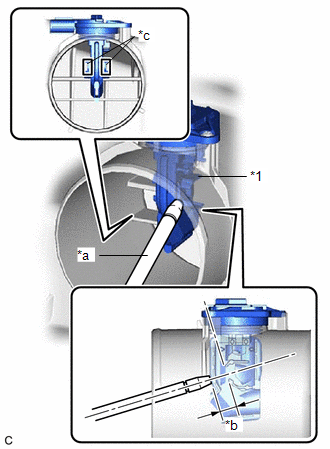
| *1 | Mass Air Flow Meter Sub-assembly |
| *a | Air Blow Gun |
| *b | 10 mm (0.394 in.) |
| *c | Airflow Hole |
| (1) Using an air blow gun, clean the hole of the mass air flow meter sub-assembly by applying approximately 10 intermittent bursts of air to the airflow hole at a pressure of approximately 392 to 981 kPa (4.0 to 10.0 kgf/cm2, 57 to 142 psi). HINT: Apply 5 intermittent bursts of air to the airflow hole at 2 locations. |
|
(c) Install the air cleaner cap sub-assembly.
3. PERFORM INITIALIZATION
(a) Perform "Inspection After Repair" after replacing the mass air flow meter sub-assembly.
Click here
 Components
COMPONENTS ILLUSTRATION *1 AIR CLEANER CAP WITH AIR CLEANER HOSE *2 MASS AIR FLOW METER SUB-ASSEMBLY *3 NO. 1 FUEL VAPOR FEED HOSE *4 NO. 2 VENTILATION HOSE ...
 Removal
REMOVAL CAUTION / NOTICE / HINT The necessary procedures (adjustment, calibration, initialization or registration) that must be performed after parts are removed and installed, or replaced during mass ...
Other materials:
Lexus RX (RX 350L, RX450h) 2016-2026 Repair Manual > Automatic Transaxle System: Check Mode Procedure
CHECK MODE PROCEDURE DESCRIPTION (a) Check mode has a higher sensitivity to malfunctions and can detect malfunctions that normal mode cannot detect. Check mode can also detect all of the malfunctions that normal mode can detect. In check mode, DTCs are detected with 1 trip detection logic. CHECK MOD ...
Lexus RX (RX 350L, RX450h) 2016-2026 Repair Manual > Roof Headlining (w/ Rear No. 2 Seat): Components
COMPONENTS ILLUSTRATION *1 DECK BOARD ASSEMBLY *2 NO. 1 DECK BOARD *3 REAR NO. 4 FLOOR BOARD *4 TONNEAU COVER ASSEMBLY ILLUSTRATION *A w/o Woofer *B w/ Woofer *1 DECK SIDE TRIM BOX LH *2 FRONT DECK FLOOR BOX *3 REAR DECK FLOOR BOX *4 REAR FLOOR FI ...
Lexus RX (RX 350L, RX450h) 2016-{YEAR} Owners Manual
- For your information
- Pictorial index
- For safety and security
- Instrument cluster
- Operation of each component
- Driving
- Lexus Display Audio system
- Interior features
- Maintenance and care
- When trouble arises
- Vehicle specifications
- For owners
Lexus RX (RX 350L, RX450h) 2016-{YEAR} Repair Manual

0.0142