Lexus RX (RX 350L, RX450h) 2016-2026 Repair Manual: High Pressure Fuel Pump Circuit Open (P123513)
DESCRIPTION
The high-pressure direct injection fuel system consists of a spill control valve, check valve, fuel relief valve, fuel pressure sensor, fuel pump assembly (for high pressure side) and fuel injector assemblies (for direct injection). The spill control valve adjusts the return volume of the high-pressure fuel. The check valve mechanically opens and closes the paths to the fuel delivery pipes. The relief valve releases the fuel back to the fuel tank if the high-pressure fuel system malfunctions. The fuel pump assembly (for high pressure side) is installed to the cylinder head cover and operated by a cam installed to the end of the intake camshaft. Rotation of the camshaft moves the pump plunger inside the fuel pump assembly (for high pressure side) up and down, pressurizing the fuel. The pressurized fuel opens the check valve and is pumped into the fuel delivery pipe.
| DTC No. | Detection Item | DTC Detection Condition | Trouble Area | MIL | Memory | Note |
|---|---|---|---|---|---|---|
| P123513 | High Pressure Fuel Pump Circuit Open | Open or short in fuel pump assembly (for high pressure side) circuit detected 60 times or more (1 trip detection logic). |
| Comes on | DTC stored | SAE Code: P1235 |
MONITOR DESCRIPTION
If an open or short in the fuel pump assembly (for high pressure side) circuit is detected after the engine is started, the ECM will illuminate the MIL and store this DTC.
MONITOR STRATEGY
| Related DTCs | P1235: Fuel pump (for high pressure side) circuit/open |
| Required Sensors/Components (Main) | Fuel pump assembly (for high pressure side) |
| Required Sensors/Components (Related) | Injector driver (ECM) |
| Frequency of Operation | Continuous |
| Duration | - |
| MIL Operation | Immediate |
| Sequence of Operation | None |
TYPICAL ENABLING CONDITIONS
| Monitor runs whenever the following DTCs are not stored | None |
| All of the following conditions are met | - |
| Time after engine start | 5 seconds or more |
| Command to injector driver relay | On |
| Output duty cycle | 5 to 95% |
| Battery voltage | 10.5 V or higher |
| Engine switch | On (IG) |
| Starter | Off |
| Engine | Running |
TYPICAL MALFUNCTION THRESHOLDS
| One of the following conditions is met | 1, 2, 3, 4 or 5 |
| 1. Both of the following conditions are met | - |
| Following condition is met | 60 time or more |
| High pressure fuel pump voltage | 4.8 V or higher |
| 2. Both of the following conditions are met | - |
| Following condition is met | 60 time or more |
| High pressure fuel pump voltage | 1.2 V or less |
| 3. Both of the following conditions are met | - |
| Following condition is met | 60 time or more |
| High pressure fuel pump current | 15 A or higher |
| 4. Both of the following conditions are met | - |
| Following condition is met | 60 time or more |
| High pressure fuel pump drive MOSFET current | 12 A or higher |
| 5. Both of the following conditions are met | - |
| Following condition is met | 60 time or more |
| High pressure fuel pump drive MOSFET voltage | 0.02 V or less |
CONFIRMATION DRIVING PATTERN
HINT:
-
After repair has been completed, clear the DTC and then check that the vehicle has returned to normal by performing the following All Readiness check procedure.
Click here
.gif)
-
When clearing the permanent DTCs, refer to the "CLEAR PERMANENT DTC" procedure.
Click here
- Connect the Techstream to the DLC3.
- Turn the engine switch on (IG).
- Turn the Techstream on.
- Clear the DTCs (even if no DTCs are stored, perform the clear DTC procedure).
- Turn the engine switch off and wait for at least 30 seconds.
- Start the engine [A].
- Idle the engine for 10 seconds [B].
- Turn the Techstream on.
- Enter the following menus: Powertrain / Engine / Trouble Codes [C].
-
Read the pending DTCs.
HINT:
- If a pending DTC is output, the system is malfunctioning.
- If a pending DTC is not output, perform the following procedure.
- Enter the following menus: Powertrain / Engine / Utility / All Readiness.
- Input the DTC: P123513.
-
Check the DTC judgment result.
Techstream Display
Description
NORMAL
- DTC judgment completed
- System normal
ABNORMAL
- DTC judgment completed
- System abnormal
INCOMPLETE
- DTC judgment not completed
- Perform driving pattern after confirming DTC enabling conditions
HINT:
- If the judgment result is NORMAL, the system is normal.
- If the judgment result is ABNORMAL, the system has a malfunction.
- If the judgment result is INCOMPLETE, perform steps [B] through [C] again.
-
[A] to [C]: Normal judgment procedure.
The normal judgment procedure is used to complete DTC judgment and also used when clearing permanent DTCs.
- When clearing the permanent DTCs, do not disconnect the cable from the battery terminal or attempt to clear the DTCs during this procedure, as doing so will clear the universal trip and normal judgment histories.
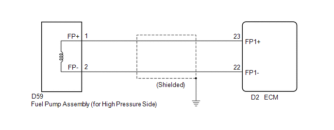
WIRING DIAGRAM
CAUTION / NOTICE / HINT
HINT:
- If the current from the INJ relay is cut because DTC P062D13 is stored, DTC P123513 will be stored even if the fuel pump assembly (for high pressure side) is normal.
- Read freeze frame data using the Techstream. The ECM records vehicle and driving condition information as freeze frame data the moment a DTC is stored. When troubleshooting, freeze frame data can help determine if the vehicle was moving or stationary, if the engine was warmed up or not, if the air fuel ratio was lean or rich, and other data from the time the malfunction occurred.
PROCEDURE
| 1. | INSPECT FUEL PUMP ASSEMBLY (FOR HIGH PRESSURE SIDE) |
(a) Inspect the fuel pump assembly (for high pressure side).
Click here
HINT:
Perform "Inspection After Repair" after replacing the fuel pump assembly (for high pressure side).
Click here
| NG | .gif) | REPLACE FUEL PUMP ASSEMBLY (FOR HIGH PRESSURE SIDE) |
|
.gif)
| 2. | CHECK HARNESS AND CONNECTOR (FUEL PUMP ASSEMBLY (FOR HIGH PRESSURE SIDE) - ECM) |
(a) Disconnect the fuel pump assembly (for high pressure side) connector.
(b) Disconnect the ECM connector.
(c) Measure the resistance according to the value(s) in the table below.
Standard Resistance:
| Tester Connection | Condition | Specified Condition |
|---|---|---|
| D59-1 (FP+) - D2-23 (FP1+) | Always | Below 1 Ω |
| D59-2 (FP-) - D2-22 (FP1-) | Always | Below 1 Ω |
| D59-1 (FP+) or D2-23 (FP1+) - Body ground and other terminals | Always | 10 kΩ or higher |
| D59-2 (FP-) or D2-22 (FP1-) - Body ground and other terminals | Always | 10 kΩ or higher |
| OK | | REPLACE ECM |
| NG | | REPAIR OR REPLACE HARNESS OR CONNECTOR |
 Bank 1 Air-Fuel Ratio Imbalance (Port) (P11EA00,...,P21A100)
DESCRIPTION Refer to DTC P030000. Click here Refer to DTC P219519. Click here DTC No. Detection Item DTC Detection Condition Trouble Area MIL Memory Note P11EA00 Bank 1 Air-Fu ...
 Engine Stall History (P160300)
DESCRIPTION After starting the engine, this DTC is stored when the engine stops without the engine switch being operated. Using the Techstream, the conditions present when the DTC was stored can be co ...
Other materials:
Lexus RX (RX 350L, RX450h) 2016-2026 Repair Manual > Airbag System: Short in Rear P/T Squib (LH) Circuit (B1925-B1928)
DESCRIPTION The rear pretensioner squib LH circuit consists of the airbag sensor assembly and rear No. 1 seat outer belt assembly LH. The airbag sensor assembly uses this circuit to deploy the pretensioner when deployment conditions are met. These DTCs are stored when a malfunction is detected in th ...
Lexus RX (RX 350L, RX450h) 2016-2026 Repair Manual > Rear Seat Reclining Control Cable: Installation
INSTALLATION PROCEDURE 1. INSTALL RECLINING REMOTE CONTROL LEVER SUB-ASSEMBLY RH (a) Engage the guide. (b) Install the 3 bolts. Torque: 18 N·m {184 kgf·cm, 13 ft·lbf} (c) Engage the 5 clamps to install the reclining remote control lever sub-assembly RH. 2. INSTALL DECK TRIM SIDE PANEL ASSEMBLY R ...
Lexus RX (RX 350L, RX450h) 2016-{YEAR} Owners Manual
- For your information
- Pictorial index
- For safety and security
- Instrument cluster
- Operation of each component
- Driving
- Lexus Display Audio system
- Interior features
- Maintenance and care
- When trouble arises
- Vehicle specifications
- For owners
Lexus RX (RX 350L, RX450h) 2016-{YEAR} Repair Manual

0.0135