Lexus RX (RX 350L, RX450h) 2016-2026 Repair Manual: MIL Circuit
DESCRIPTION
The Malfunction Indicator Lamp (MIL) is used to indicate vehicle malfunctions detected by the ECM.
The MIL operation can be checked visually. When the engine switch is first turned on (IG), the MIL should be illuminated and should then turn off after the engine is started. If the MIL remains illuminated or is not illuminated, conduct the following troubleshooting procedure using the Techstream.
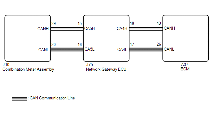
WIRING DIAGRAM
PROCEDURE
| 1. | CHECK THAT MIL IS ILLUMINATED |
(a) Perform troubleshooting in accordance with the table below.
| MIL | Condition | Proceed to |
|---|---|---|
| Illuminates → Turns off | Engine switch on (IG) → engine is started | A |
| Other than above | - | B |
| A | .gif) | CHECK FOR INTERMITTENT PROBLEMS |
|
.gif)
| 2. | CHECK COMMUNICATION BETWEEN TECHSTREAM AND ECM |
(a) Connect the Techstream to the DLC3.
(b) Turn the engine switch on (IG).
(c) Turn the Techstream on.
(d) Check the communication between the Techstream and ECM.
HINT:
It can be checked using the "Engine" item of the Data List.
| Result | Proceed to |
|---|---|
| Communication is possible | A |
| Communication is not possible | B |
| B | | GO TO VC OUTPUT CIRCUIT |
|
| 3. | CHECK WHETHER DTC OUTPUT RECURS |
(a) Connect the Techstream to the DLC3.
(b) Turn the engine switch on (IG).
(c) Turn the Techstream on.
(d) Enter the following menus: System Select / Health Check.
(e) Check if any DTCs have been detected. Note down any DTCs.
| Result | Proceed to |
|---|---|
| DTCs are not output | A |
| Any DTCs is output | B |
HINT:
Check for detected DTCs output from other ECUs which relate to the MIL.
| B | | REPAIR CIRCUIT INDICATED BY OUTPUT |
|
| 4. | PERFORM ACTIVE TEST USING TECHSTREAM |
(a) Connect the Techstream to the DLC3.
(b) Turn the engine switch on (IG).
(c) Turn the Techstream on.
(d) Enter the following menus: Body Electrical / Combination Meter / Active Test / Check Engine Indicator.
Body Electrical > Combination Meter > Active Test| Tester Display |
|---|
| Check Engine Indicator |
(e) Check the status of the MIL while performing the Active Test.
| Result | Proceed to |
|---|---|
| Changes | A |
| Does not change | B |
| A | | REPLACE ECM |
.gif)
| B | | REPLACE COMBINATION METER ASSEMBLY |
 Brake Override System
DESCRIPTION When the vehicle is being driven, depressing the accelerator pedal sensor assembly and brake pedal will activate the brake override system to restrict engine output. The conditions for act ...
 Ignition Circuit
DESCRIPTION A direct ignition system is used on this vehicle. The direct ignition system is a 1 cylinder ignition system which ignites one cylinder with one ignition coil. In the 1 cylinder ignition s ...
Other materials:
Lexus RX (RX 350L, RX450h) 2016-2026 Repair Manual > Audio And Visual System (for 8 Inch Display): Illumination Circuit
DESCRIPTION Power is supplied to the radio receiver assembly and steering pad switch assembly illumination when the light control switch is in the tail or head position. WIRING DIAGRAM CAUTION / NOTICE / HINT NOTICE:
The vehicle is equipped with a Supplemental Restraint System (SRS) which includ ...
Lexus RX (RX 350L, RX450h) 2016-2026 Repair Manual > Panoramic View Monitor System: "CHK" message(s) are displayed on the SIGNAL CHECK screen.
DESCRIPTION On the SIGNAL CHECK screen, it is possible to check if the signals sent to the parking assist ECU are normal. Click here HINT:
On the SIGNAL CHECK screen, "OK" (blue) is displayed for items with a normal inspection result or input state.
On the SIGNAL CHECK screen, "CHK" (red) is ...
Lexus RX (RX 350L, RX450h) 2016-{YEAR} Owners Manual
- For your information
- Pictorial index
- For safety and security
- Instrument cluster
- Operation of each component
- Driving
- Lexus Display Audio system
- Interior features
- Maintenance and care
- When trouble arises
- Vehicle specifications
- For owners
Lexus RX (RX 350L, RX450h) 2016-{YEAR} Repair Manual

0.0119