Lexus RX (RX 350L, RX450h) 2016-2026 Repair Manual: Ignition Circuit
DESCRIPTION
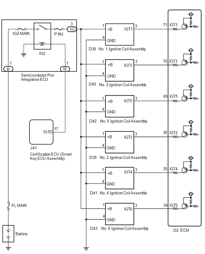
A direct ignition system is used on this vehicle. The direct ignition system is a 1 cylinder ignition system which ignites one cylinder with one ignition coil. In the 1 cylinder ignition system, one spark plug is connected to the end of the secondary winding. High voltage is generated in the secondary winding and is applied directly to the spark plug. The spark of the spark plug passes from the center electrode to the ground electrode.
The ECM determines the ignition timing and transmits the ignition signals for each cylinder. Using the ignition signal, the ECM turns on and off the power transistor inside the igniter, which switches on and off a current to the primary coil. When the current to the primary coil is cut off, high voltage is generated in the secondary coil and this voltage is applied to the spark plugs to create sparks inside the cylinders.
WIRING DIAGRAM
CAUTION / NOTICE / HINT
NOTICE:
Inspect the fuses for circuits related to this system before performing the following procedure.
HINT:
Perform a spark test before proceeding. If there is no spark for any cylinder, inspect this circuit.
Click here .gif)
PROCEDURE
| 1. | CHECK TERMINAL VOLTAGE (POWER SOURCE OF IGNITION COIL ASSEMBLY) |
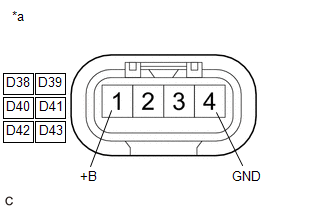
| *a | Front view of wire harness connector (to Ignition Coil Assembly) |
(a) Disconnect the ignition coil assembly connector.
(b) Turn the engine switch on (IG).
(c) Measure the voltage according to the value(s) in the table below.
Standard Voltage:
| Tester Connection | Condition | Specified Condition |
|---|---|---|
| D38-1 (+B) - D38-4 (GND) | Engine switch on (IG) | 11 to 14 V |
| D39-1 (+B) - D39-4 (GND) | Engine switch on (IG) | 11 to 14 V |
| D40-1 (+B) - D40-4 (GND) | Engine switch on (IG) | 11 to 14 V |
| D41-1 (+B) - D41-4 (GND) | Engine switch on (IG) | 11 to 14 V |
| D42-1 (+B) - D42-4 (GND) | Engine switch on (IG) | 11 to 14 V |
| D43-1 (+B) - D43-4 (GND) | Engine switch on (IG) | 11 to 14 V |
| NG | .gif) | GO TO STEP 3 |
|
.gif)
| 2. | CHECK HARNESS AND CONNECTOR (IGNITION COIL ASSEMBLY - ECM) |
(a) Disconnect the ignition coil assembly connector.
(b) Disconnect the ECM connector.
(c) Measure the resistance according to the value(s) in the table below.
Standard Resistance:
| Tester Connection | Condition | Specified Condition |
|---|---|---|
| D38-3 (IGT1) - D2-71 (IGT1) | Always | Below 1 Ω |
| D39-3 (IGT2) - D2-36 (IGT2) | Always | Below 1 Ω |
| D40-3 (IGT3) - D2-70 (IGT3) | Always | Below 1 Ω |
| D41-3 (IGT4) - D2-35 (IGT4) | Always | Below 1 Ω |
| D42-3 (IGT5) - D2-69 (IGT5) | Always | Below 1 Ω |
| D43-3 (IGT6) - D2-34 (IGT6) | Always | Below 1 Ω |
| D38-3 (IGT1) or D2-71 (IGT1) - Body ground and other terminals | Always | 10 kΩ or higher |
| D39-3 (IGT2) or D2-36 (IGT2) - Body ground and other terminals | Always | 10 kΩ or higher |
| D40-3 (IGT3) or D2-70 (IGT3) - Body ground and other terminals | Always | 10 kΩ or higher |
| D41-3 (IGT4) or D2-35 (IGT4) - Body ground and other terminals | Always | 10 kΩ or higher |
| D42-3 (IGT5) or D2-69 (IGT5) - Body ground and other terminals | Always | 10 kΩ or higher |
| D43-3 (IGT6) or D2-34 (IGT6) - Body ground and other terminals | Always | 10 kΩ or higher |
| OK | | REPLACE ECM |
| NG | | REPAIR OR REPLACE HARNESS OR CONNECTOR |
| 3. | CHECK HARNESS AND CONNECTOR (IGNITION COIL ASSEMBLY - BODY GROUND) |
(a) Disconnect the ignition coil assembly connector.
(b) Measure the resistance according to the value(s) in the table below.
Standard Resistance:
| Tester Connection | Condition | Specified Condition |
|---|---|---|
| D38-4 (GND) - Body ground | Always | Below 1 Ω |
| D39-4 (GND) - Body ground | Always | Below 1 Ω |
| D40-4 (GND) - Body ground | Always | Below 1 Ω |
| D41-4 (GND) - Body ground | Always | Below 1 Ω |
| D42-4 (GND) - Body ground | Always | Below 1 Ω |
| D43-4 (GND) - Body ground | Always | Below 1 Ω |
| NG | | REPAIR OR REPLACE HARNESS OR CONNECTOR |
|
| 4. | CHECK HARNESS AND CONNECTOR (SEMICONDUCTOR PWR INTEGRATION ECU - IGNITION COIL ASSEMBLY) |
(a) Disconnect the semiconductor pwr integration ECU connector.
(b) Disconnect the ignition coil assembly connector.
(c) Measure the resistance according to the value(s) in the table below.
Standard Resistance:
| Tester Connection | Condition | Specified Condition |
|---|---|---|
| 1G-3 - D38-1 (+B) | Always | Below 1 Ω |
| 1G-3 - D39-1 (+B) | Always | Below 1 Ω |
| 1G-3 - D40-1 (+B) | Always | Below 1 Ω |
| 1G-3 - D41-1 (+B) | Always | Below 1 Ω |
| 1G-3 - D42-1 (+B) | Always | Below 1 Ω |
| 1G-3 - D43-1 (+B) | Always | Below 1 Ω |
| 1G-3 or D38-1 (+B) - Body ground and other terminals | Always | 10 kΩ or higher |
| 1G-3 or D39-1 (+B) - Body ground and other terminals | Always | 10 kΩ or higher |
| 1G-3 or D40-1 (+B) - Body ground and other terminals | Always | 10 kΩ or higher |
| 1G-3 or D41-1 (+B) - Body ground and other terminals | Always | 10 kΩ or higher |
| 1G-3 or D42-1 (+B) - Body ground and other terminals | Always | 10 kΩ or higher |
| 1G-3 or D43-1 (+B) - Body ground and other terminals | Always | 10 kΩ or higher |
| OK | | REPLACE SEMICONDUCTOR POWER INTEGRATION ECU |
| NG | | REPAIR OR REPLACE HARNESS OR CONNECTOR |
 MIL Circuit
DESCRIPTION The Malfunction Indicator Lamp (MIL) is used to indicate vehicle malfunctions detected by the ECM. The MIL operation can be checked visually. When the engine switch is first turned on (IG) ...
 Drive Start Control
DESCRIPTION The drive start control is controlled by the ECM. If the ECM determines that the shift lever and accelerator pedal are operated abnormally, engine output is restricted and, when necessary, ...
Other materials:
Lexus RX (RX 350L, RX450h) 2016-2026 Repair Manual > Panoramic View Monitor System: Camera Position Adjustment Incomplete (C1697)
DESCRIPTION This DTC is stored when the parking assist ECU judges that the camera initial setting has not been memorized (camera view adjustment is incomplete). DTC No. Detection Item DTC Detection Condition Trouble Area C1697 Camera Position Adjustment Incomplete Camera initial set ...
Lexus RX (RX 350L, RX450h) 2016-2026 Repair Manual > Cylinder Block: Reassembly
REASSEMBLY PROCEDURE 1. INSTALL NO. 1 OIL NOZZLE SUB-ASSEMBLY (a) Using a 5 mm hexagon socket wrench, install the 3 No. 1 oil nozzle sub-assemblies to the cylinder block sub-assembly with the 3 bolts. Torque: 9.0 N·m {92 kgf·cm, 80 in·lbf} 2. INSTALL PISTON HINT: Perform this proc ...
Lexus RX (RX 350L, RX450h) 2016-{YEAR} Owners Manual
- For your information
- Pictorial index
- For safety and security
- Instrument cluster
- Operation of each component
- Driving
- Lexus Display Audio system
- Interior features
- Maintenance and care
- When trouble arises
- Vehicle specifications
- For owners
Lexus RX (RX 350L, RX450h) 2016-{YEAR} Repair Manual

0.0109