Lexus RX (RX 350L, RX450h) 2016-2026 Repair Manual: Disassembly
DISASSEMBLY
CAUTION / NOTICE / HINT
The necessary procedures (adjustment, calibration, initialization, or registration) that must be performed after parts are removed and installed, or replaced during engine unit removal/installation are shown below.
Necessary Procedure After Parts Removed/Installed/Replaced| Replaced Part or Performed Procedure | Necessary Procedure | Effect/Inoperative Function when Necessary Procedure not Performed | Link |
|---|---|---|---|
|
*1: When performing learning using the Techstream.
Click here | |||
| Disconnect cable from negative battery terminal | Memorize steering angle neutral point | Lane Control System | |
| Pre-collision system | |||
| Intelligent clearance sonar system*1 | |||
| Lighting system (w/ Automatic Headlight Beam Level Control System) | | ||
| Parking assist monitor system | | ||
| Panoramic view monitor system | | ||
| Initialize back door lock | Power door lock control system | | |
| Reset back door close position | Power Back Door System (w/ Outside Door Control Switch) | | |
| Replacement of ECM | Vehicle Identification Number (VIN) registration | MIL comes on | |
| ECU Communication ID Registration (Immobiliser system) | Engine start function | | |
| Perform code registration (Immobiliser system) |
| | |
| Inspection After Repair |
| |
| Replacement of automatic transaxle assembly | Perform the following procedures in the order shown:
|
| for U881E Registration: for U881E Initialization: for U881F Registration: for U881F Initialization: |
| Replacement of ECM (If possible, read the transaxle compensation code from the previous ECM) | Perform the following procedures in the order shown:
| ||
| Replacement of ECM (If impossible, read the transaxle compensation code from the previous ECM) | Perform the following procedures in the order shown:
| ||
| Front wheel alignment adjustment | Calibration |
| |
| Suspension, tires, etc. (The vehicle height changes because of suspension or tire replacement) |
|
| |
| Rear television camera assembly optical axis (Back camera position setting) | Parking assist monitor system | for Initialization: for Calibration: | |
| Panoramic view monitor system | for Initialization: for Calibration: | |
| Initialize No. 1 headlight ECU sub-assembly LH | Lighting System (w/ Automatic Headlight Beam Level Control System) | | |
.gif)
PROCEDURE
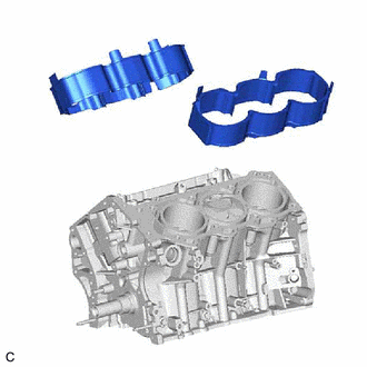
1. REMOVE CYLINDER BLOCK WATER JACKET SPACER
| (a) Remove the cylinder block water jacket spacer and cylinder block water jacket spacer LH from the cylinder block sub-assembly. |
|
2. REMOVE PISTON SUB-ASSEMBLY WITH CONNECTING ROD
(a) Check that the matchmarks on the connecting rod sub-assembly and connecting rod cap are aligned.
HINT:
The matchmarks on the connecting rod sub-assembly and connecting rod cap are guides for correct reassembly.
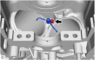
(b) Remove the 2 connecting rod cap bolts.
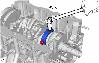
.png) | Front of Engine |
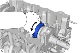
| (c) Using the 2 removed connecting rod cap bolts, remove the connecting rod cap and lower connecting rod bearing by wiggling the connecting rod cap right and left. HINT: Keep the lower connecting rod bearing installed to the connecting rod cap. |
|
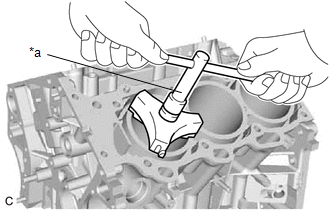
| (d) Using a ridge reamer, remove all of the carbon from the top of the cylinder. |
|
(e) Push the piston, connecting rod sub-assembly and upper connecting rod bearing through the top of the cylinder block sub-assembly.
HINT:
- Keep the connecting rod bearing, connecting rod sub-assembly and connecting rod cap together.
- Arrange the removed parts in such a way that they can be reinstalled to their original locations.
3. REMOVE CONNECTING ROD BEARING
(a) Remove the connecting rod bearings from the connecting rod sub-assembly and connecting rod cap.
HINT:
Arrange the removed parts in such a way that they can be reinstalled to their original locations.
4. REMOVE PISTON RING SET
| (a) Using a piston ring expander, remove the No. 1 compression ring and No. 2 compression ring. |
|
(b) Remove the oil ring expander and 2 side rails by hand.
HINT:
Arrange the removed parts in such a way that they can be reinstalled to their original locations.
5. REMOVE PISTON
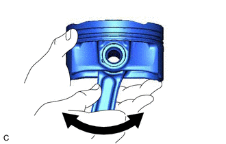
| (a) Check the fitting condition between the piston and piston pin. (1) Try to move the piston back and forth on the piston pin. HINT: If abnormal movement is felt, replace the piston and piston pin as a set. |
|
(b) Remove the connecting rod sub-assembly from the piston.
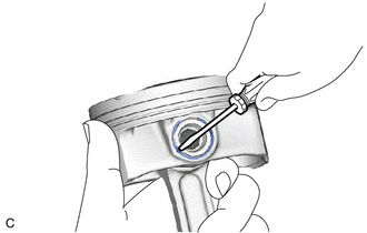
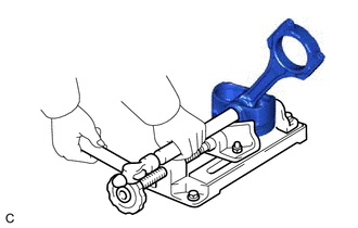
(1) Using a screwdriver, pry out the piston pin hole snap ring (front side).
NOTICE:
- Do not remove the piston pin hole snap ring (rear side) unless it has to be replaced.
- Be careful not to damage the piston when removing the piston pin hole snap ring (rear side).
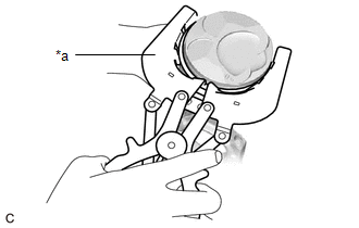
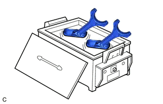
| (2) Gradually heat the piston to approximately 80°C (176°F). CAUTION: Be sure to wear protective gloves. |
|
| (3) Using a brass bar and a hammer, lightly tap out the piston pin and remove the connecting rod sub-assembly. HINT:
|
|
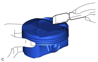
| (c) Using a gasket scraper, remove any carbon from the piston top. NOTICE: Be careful not to scratch the piston. |
|
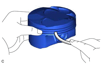
| (d) Using a groove cleaning tool or a broken ring, clean the piston ring grooves. |
|
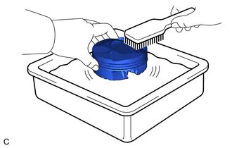
| (e) Using solvent and a brush, thoroughly clean the piston. NOTICE: Do not use a wire brush. |
|
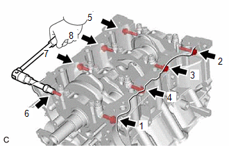
6. REMOVE CRANKSHAFT
| (a) Uniformly loosen and remove the 8 crankshaft bearing cap set bolts and 8 seal washers in several steps in the order shown in the illustration. |
|
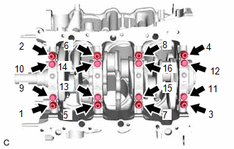
| (b) Uniformly loosen the 16 crankshaft bearing cap set bolts in several steps in the order shown in the illustration. |
|
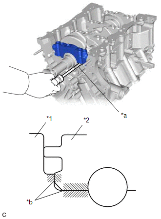
| (c) Using a screwdriver with its tip wrapped with protective tape, pry out the crankshaft bearing caps. Remove the 4 crankshaft bearing caps and lower crankshaft bearings. NOTICE:
|
|
(d) Remove the crankshaft.
7. REMOVE CRANKSHAFT BEARING
(a) Remove the upper crankshaft bearings and lower crankshaft bearings.
HINT:
Arrange the removed parts in such a way that they can be reinstalled to their original locations.
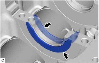
8. REMOVE CRANKSHAFT THRUST WASHER SET
| (a) Remove the crankshaft thrust washer set from the cylinder block sub-assembly. |
|
9. REMOVE NO. 1 OIL NOZZLE SUB-ASSEMBLY
| (a) Using a 5 mm hexagon socket wrench, remove the 3 bolts and 3 No. 1 oil nozzle sub-assemblies. |
|
(b) Check the 3 No. 1 oil nozzle sub-assemblies for damage or clogging.
HINT:
If there is damage or clogs, replace the No. 1 oil nozzle sub-assembly.
 Replacement
REPLACEMENT PROCEDURE 1. REPLACE STRAIGHT PIN NOTICE: If a straight pin is deformed, replace it. (a) Using a plastic hammer, tap in new straight pins to the cylinder block sub-assembly. *a Front ...
 Inspection
INSPECTION PROCEDURE 1. INSPECT CONNECTING ROD THRUST CLEARANCE (a) Install the connecting rod cap. Click here (b) Using a dial indicator, measure the thrust clearance while moving the connecting ...
Other materials:
Lexus RX (RX 350L, RX450h) 2016-2026 Repair Manual > Washer Level Warning Switch: Inspection
INSPECTION PROCEDURE 1. INSPECT LEVEL WARNING SWITCH ASSEMBLY HINT: This check should be performed with the level warning switch assembly installed on the washer jar. (a) Fill the washer jar with washer fluid. *a Component without harness connected (Level Warning Switch Assembly) ...
Lexus RX (RX 350L, RX450h) 2016-2026 Repair Manual > Exterior Panels / Trim: Wheel Opening Moulding(for Front Side)
ComponentsCOMPONENTS ILLUSTRATION *1 FRONT FENDER MOULDING SUB-ASSEMBLY *2 FRONT FENDER SPLASH SHIELD SUB-ASSEMBLY InstallationINSTALLATION CAUTION / NOTICE / HINT HINT:
Use the same procedure for the RH side and LH side.
The following procedure is for the LH side.
PROCEDURE 1. ...
Lexus RX (RX 350L, RX450h) 2016-{YEAR} Owners Manual
- For your information
- Pictorial index
- For safety and security
- Instrument cluster
- Operation of each component
- Driving
- Lexus Display Audio system
- Interior features
- Maintenance and care
- When trouble arises
- Vehicle specifications
- For owners
Lexus RX (RX 350L, RX450h) 2016-{YEAR} Repair Manual

0.0131