Lexus RX (RX 350L, RX450h) 2016-2026 Repair Manual: Disassembly
DISASSEMBLY
CAUTION / NOTICE / HINT
The necessary procedures (adjustment, calibration, initialization, or registration) that must be performed after parts are removed and installed, or replaced during engine unit removal/installation are shown below.
Necessary Procedure After Parts Removed/Installed/Replaced| Replaced Part or Performed Procedure | Necessary Procedure | Effect/Inoperative Function when Necessary Procedure not Performed | Link |
|---|---|---|---|
|
*1: When performing learning using the Techstream.
Click here | |||
| Disconnect cable from negative battery terminal | Memorize steering angle neutral point | Lane Control System | |
| Pre-collision system | |||
| Intelligent clearance sonar system*1 | |||
| Lighting system (w/ Automatic Headlight Beam Level Control System) | | ||
| Parking assist monitor system | | ||
| Panoramic view monitor system | | ||
| Initialize back door lock | Power door lock control system | | |
| Reset back door close position | Power Back Door System (w/ Outside Door Control Switch) | | |
| Replacement of ECM | Vehicle Identification Number (VIN) registration | MIL comes on | |
| ECU Communication ID Registration (Immobiliser system) | Engine start function | | |
| Perform code registration (Immobiliser system) |
| | |
| Inspection After Repair |
| |
| Replacement of automatic transaxle assembly | Perform the following procedures in the order shown:
|
| for U881E Registration: for U881E Initialization: for U881F Registration: for U881F Initialization: |
| Replacement of ECM (If possible, read the transaxle compensation code from the previous ECM) | Perform the following procedures in the order shown:
| ||
| Replacement of ECM (If impossible, read the transaxle compensation code from the previous ECM) | Perform the following procedures in the order shown:
| ||
| Front wheel alignment adjustment | Calibration |
| |
| Suspension, tires, etc. (The vehicle height changes because of suspension or tire replacement) |
|
| |
| Rear television camera assembly optical axis (Back camera position setting) | Parking assist monitor system | for Initialization: for Calibration: | |
| Panoramic view monitor system | for Initialization: for Calibration: | |
| Initialize No. 1 headlight ECU sub-assembly LH | Lighting System (w/ Automatic Headlight Beam Level Control System) | | |
.gif)
PROCEDURE
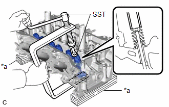
1. REMOVE INTAKE VALVE
| (a) Using SST and wooden blocks, compress the inner compression spring and remove the 6 valve spring retainer locks from the valve spring retainer. SST: 09202-70020 09202-01010 09202-01020 SST: 09202-00021 HINT: Arrange the removed parts in such a way that they can be reinstalled to their original locations. |
|
(b) Remove the 6 valve spring retainers, 6 inner compression springs and 6 intake valves from the cylinder head LH.
HINT:
Arrange the removed parts in such a way that they can be reinstalled to their original locations.
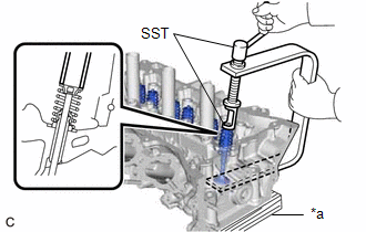
2. REMOVE EXHAUST VALVE
| (a) Using SST and wooden blocks, compress the inner compression spring and remove the 6 valve spring retainer locks from the valve spring retainer. SST: 09202-70020 09202-01010 09202-01020 SST: 09202-00021 HINT: Arrange the removed parts in such a way that they can be reinstalled to their original locations. |
|
(b) Remove the 6 valve spring retainers, 6 inner compression springs and 6 exhaust valves from the cylinder head LH.
HINT:
Arrange the removed parts in such a way that they can be reinstalled to their original locations.
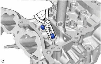
3. REMOVE INTAKE VALVE STEM OIL SEAL
| (a) Using needle-nose pliers, remove the 6 intake valve stem oil seals from the intake valve guide bush. |
|
4. REMOVE EXHAUST VALVE STEM OIL SEAL
HINT:
Use the same procedure as for the intake side.
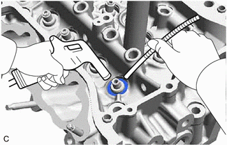
5. REMOVE VALVE SPRING SEAT
| (a) Using compressed air and a Magnet Hand, remove the 12 valve spring seats by blowing air onto them from the cylinder head LH. HINT: Arrange the removed parts in such a way that they can be reinstalled to their original locations. |
|
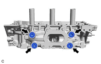
6. REMOVE NO. 1 STRAIGHT SCREW PLUG
NOTICE:
If coolant leaks from a No. 1 straight screw plug or a plug is corroded, replace it.
| (a) Using a 10 mm hexagon socket wrench, remove the 2 No. 1 straight screw plugs and 2 water hole gaskets from the cylinder head LH. |
|
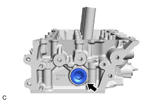
7. REMOVE NO. 2 STRAIGHT SCREW PLUG
NOTICE:
If coolant leaks from a No. 2 straight screw plug or a plug is corroded, replace it.
| (a) Using a 14 mm hexagon socket wrench, remove the No. 2 straight screw plug and cylinder head screw plug gasket from the cylinder head LH. |
|
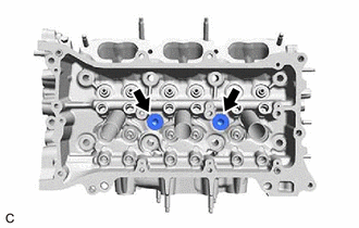
8. REMOVE NO. 3 STRAIGHT SCREW PLUG
NOTICE:
If coolant leaks from a No. 3 straight screw plug or a plug is corroded, replace it.
| (a) Using a 10 mm hexagon socket wrench, remove the 4 No. 3 straight screw plugs and 4 cylinder head screw plug gaskets from the cylinder head LH. |
|
 Components
COMPONENTS ILLUSTRATION *A w/ Stud Bolt - - *1 VALVE SPRING RETAINER LOCK *2 VALVE SPRING RETAINER *3 INNER COMPRESSION SPRING *4 INTAKE VALVE STEM OIL SEAL *5 VALV ...
 Inspection
INSPECTION CAUTION / NOTICE / HINT HINT:
Use the same procedure for bank 1 and bank 2.
The following procedure is for bank 2.
PROCEDURE 1. INSPECT CYLINDER HEAD LH (a) Using a precision straig ...
Other materials:
Lexus RX (RX 350L, RX450h) 2016-2026 Repair Manual > Electrical Key Oscillator(for Luggage Compartment): Removal
REMOVAL PROCEDURE 1. REMOVE TONNEAU COVER ASSEMBLY Click here 2. REMOVE DECK BOARD ASSEMBLY Click here 3. REMOVE REAR DECK FLOOR BOX Click here 4. REMOVE REAR NO. 4 FLOOR BOARD Click here 5. REMOVE FRONT DECK FLOOR BOX Click here 6. REMOVE NO. 3 INDOOR ELECTRICAL KEY ANTENNA ...
Lexus RX (RX 350L, RX450h) 2016-2026 Repair Manual > Mirror (ext): Outer Rear View Mirror Cover
ComponentsCOMPONENTS ILLUSTRATION *1 NO. 1 OUTER MIRROR COVER *2 OUTER MIRROR RemovalREMOVAL CAUTION / NOTICE / HINT HINT:
Use the same procedure for the RH side and LH side.
The following procedure is for the LH side.
PROCEDURE 1. REMOVE OUTER MIRROR Click here 2. REMOVE NO. ...
Lexus RX (RX 350L, RX450h) 2016-{YEAR} Owners Manual
- For your information
- Pictorial index
- For safety and security
- Instrument cluster
- Operation of each component
- Driving
- Lexus Display Audio system
- Interior features
- Maintenance and care
- When trouble arises
- Vehicle specifications
- For owners
Lexus RX (RX 350L, RX450h) 2016-{YEAR} Repair Manual

0.0098