Lexus RX (RX 350L, RX450h) 2016-2026 Repair Manual: Removal
REMOVAL
CAUTION / NOTICE / HINT
The necessary procedures (adjustment, calibration, initialization, or registration) that must be performed after parts are removed and installed, or replaced during engine unit removal/installation are shown below.
Necessary Procedure After Parts Removed/Installed/Replaced| Replaced Part or Performed Procedure | Necessary Procedure | Effect/Inoperative Function when Necessary Procedure not Performed | Link |
|---|---|---|---|
|
*1: When performing learning using the Techstream.
Click here | |||
| Disconnect cable from negative battery terminal | Memorize steering angle neutral point | Lane Control System | |
| Pre-collision system | |||
| Intelligent clearance sonar system*1 | |||
| Lighting system (w/ Automatic Headlight Beam Level Control System) | | ||
| Parking assist monitor system | | ||
| Panoramic view monitor system | | ||
| Initialize back door lock | Power door lock control system | | |
| Reset back door close position | Power Back Door System (w/ Outside Door Control Switch) | | |
| Replacement of ECM | Vehicle Identification Number (VIN) registration | MIL comes on | |
| ECU Communication ID Registration (Immobiliser system) | Engine start function | | |
| Perform code registration (Immobiliser system) |
| | |
| Inspection After Repair |
| |
| Replacement of automatic transaxle assembly | Perform the following procedures in the order shown:
|
| for U881E Registration: for U881E Initialization: for U881F Registration: for U881F Initialization: |
| Replacement of ECM (If possible, read the transaxle compensation code from the previous ECM) | Perform the following procedures in the order shown:
| ||
| Replacement of ECM (If impossible, read the transaxle compensation code from the previous ECM) | Perform the following procedures in the order shown:
| ||
| Front wheel alignment adjustment | Calibration |
| |
| Suspension, tires, etc. (The vehicle height changes because of suspension or tire replacement) |
|
| |
| Rear television camera assembly optical axis (Back camera position setting) | Parking assist monitor system | for Initialization: for Calibration: | |
| Panoramic view monitor system | for Initialization: for Calibration: | |
| Initialize No. 1 headlight ECU sub-assembly LH | Lighting System (w/ Automatic Headlight Beam Level Control System) | | |
PROCEDURE
1. REMOVE KNOCK CONTROL SENSOR
Click here .gif)
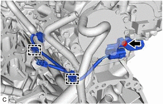
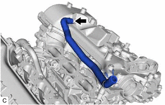
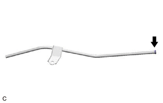
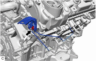
2. REMOVE SENSOR WIRE
| (a) Disengage the 2 clamps and remove the bolt and sensor wire from the water inlet pipe. |
|
3. REMOVE IGNITION COIL ASSEMBLY
Click here
4. REMOVE VACUUM PUMP ASSEMBLY
Click here
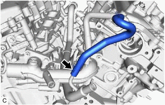
5. REMOVE NO. 3 WATER BY-PASS HOSE
| (a) Slide the clip and remove the No. 3 water by-pass hose from the water inlet pipe. |
|
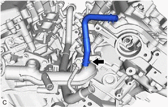
6. REMOVE NO. 2 WATER BY-PASS HOSE
| (a) Slide the clip and remove the No. 2 water by-pass hose from the water outlet. |
|
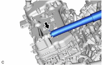
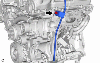
7. REMOVE VENTILATION HOSE
| (a) Slide the clip and remove the ventilation hose from the PCV valve (ventilation valve sub-assembly). |
|
8. REMOVE NO. 2 VENTILATION HOSE
| (a) Slide the clip and remove the No. 2 ventilation hose from the cylinder head cover sub-assembly. |
|
9. REMOVE V-RIBBED BELT
Click here
10. REMOVE GENERATOR ASSEMBLY
-
for 180A Type:
Click here
-
for 150A Type:
Click here
11. REMOVE COMPRESSOR AND MAGNETIC CLUTCH
Click here
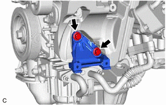
12. REMOVE NO. 1 COMPRESSOR MOUNTING BRACKET
| (a) Remove the 2 bolts and No. 1 compressor mounting bracket from the cylinder block sub-assembly. |
|
13. REMOVE NO. 2 IDLER PULLEY SUB-ASSEMBLY
Click here
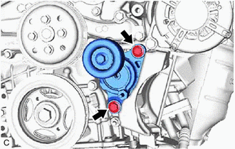
14. REMOVE V-RIBBED BELT TENSIONER ASSEMBLY
| (a) Remove the 2 bolts and V-ribbed belt tensioner assembly. |
|
15. REMOVE WATER PUMP PULLEY
Click here
16. REMOVE ENGINE OIL LEVEL DIPSTICK GUIDE
(a) Remove the engine oil level dipstick from the engine oil level dipstick guide.
| (b) Remove the bolt and engine oil level dipstick guide from the camshaft housing sub-assembly LH and oil pan sub-assembly. |
|
| (c) Remove the engine oil level dipstick guide O-ring from the engine oil level dipstick guide. |
|
17. REMOVE NO. 5 CYLINDER BLOCK INSULATOR (w/ Oil Cooler)
| (a) Remove the No. 5 cylinder block insulator from the engine assembly. |
|
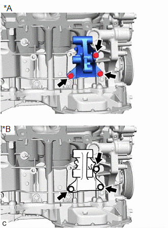
18. REMOVE DRIVE SHAFT BEARING BRACKET (for 2WD)
| (a) Remove the 3 bolts and drive shaft bearing bracket from the cylinder block sub-assembly. |
|
19. REMOVE NO. 2 TRANSFER STIFFENER PLATE (for AWD)
| (a) Remove the 3 bolts and No. 2 transfer stiffener plate from the cylinder block sub-assembly. |
|
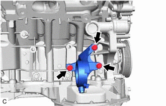
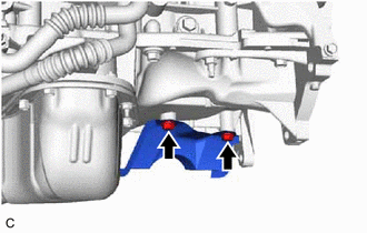
20. REMOVE NO. 1 EXHAUST PIPE SUPPORT BRACKET
| (a) Remove the 2 bolts and No. 1 exhaust pipe support bracket from the oil pan sub-assembly. |
|
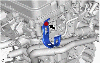
21. REMOVE WIRE HARNESS CLAMP BRACKET
| (a) Remove the bolt and wire harness clamp bracket from the camshaft housing sub-assembly. |
|
22. REMOVE RADIATOR PIPE CLAMP
| (a) Remove the bolt and radiator pipe clamp from the camshaft housing sub-assembly LH. |
|
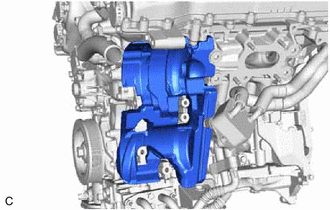
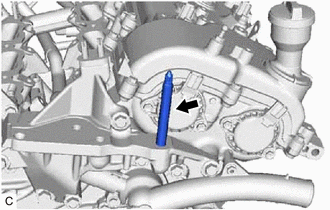
23. REMOVE STUD BOLT
NOTICE:
If a stud bolt is deformed or its threads are damaged, replace it.
| (a) Using an 8 mm socket wrench, remove the stud bolt from the front No. 1 engine mounting bracket LH. |
|
 Components
COMPONENTS ILLUSTRATION *A for 2WD *B for AWD *C Type A *D Type B *E w/ Oil Cooler - - *1 IGNITION COIL ASSEMBLY *2 VACUUM PUMP ASSEMBLY *3 NO. 2 WATER BY ...
 Inspection
INSPECTION PROCEDURE 1. INSPECT NO. 1 VALVE ROCKER ARM SUB-ASSEMBLY (a) Turn the roller by hand to check that it turns smoothly. HINT: If the roller does not turn smoothly, replace the No. 1 valve ...
Other materials:
Lexus RX (RX 350L, RX450h) 2016-2026 Repair Manual > Seat Heater System: Problem Symptoms Table
PROBLEM SYMPTOMS TABLE NOTICE:
If the battery voltage is low, the seat heater system may not operate. When "Operation of Electrical Items Restricted." is displayed on the multi-information display in the combination meter assembly, inspect the battery, referring to On-vehicle Inspection for the c ...
Lexus RX (RX 350L, RX450h) 2016-2026 Repair Manual > Lighting System (w/ Automatic Headlight Beam Level Control System): Right Headlight ECU Malfunction (B242C,B242D)
DESCRIPTION The No. 1 headlight ECU sub-assembly LH stores a DTC if it detects an internal malfunction. for Multiple Beam Headlight DTC No. Detection Item DTC Detection Condition Trouble Area DTC Output from B242C Right Headlight ECU Malfunction
The engine switch is on (IG).
...
Lexus RX (RX 350L, RX450h) 2016-{YEAR} Owners Manual
- For your information
- Pictorial index
- For safety and security
- Instrument cluster
- Operation of each component
- Driving
- Lexus Display Audio system
- Interior features
- Maintenance and care
- When trouble arises
- Vehicle specifications
- For owners
Lexus RX (RX 350L, RX450h) 2016-{YEAR} Repair Manual

0.0127