Lexus RX (RX 350L, RX450h) 2016-2026 Repair Manual: Installation
INSTALLATION
CAUTION / NOTICE / HINT
CAUTION:
- The engine assembly with transaxle is very heavy. Be sure to follow the procedure described in the repair manual, or the engine lifter may suddenly drop or the engine assembly with transaxle may fall off the engine lifter.
- To prevent burns, do not touch the engine, exhaust manifold or other high temperature components while the engine is hot.
PROCEDURE
1. INSTALL ENGINE MOUNTING INSULATOR LH
HINT:
Perform this procedure only when replacement of the engine mounting insulator LH is necessary.
| (a) Install the engine mounting insulator LH to the vehicle body with the 5 bolts. Torque: 71 N·m {724 kgf·cm, 52 ft·lbf} NOTICE: Temporarily tighten the bolt (A), then tighten the bolt (B) before tightening the order 4 bolts. |
|
2. INSTALL ENGINE MOUNTING SPACER
HINT:
Perform this procedure only when replacement of the engine mounting spacer is necessary.
(a) Install the engine mounting spacer to the vehicle body with the 2 bolts.
Torque:
71 N·m {724 kgf·cm, 52 ft·lbf}
3. INSTALL ENGINE MOUNTING INSULATOR SUB-ASSEMBLY RH
HINT:
Perform this procedure only when replacement of the engine mounting insulator sub-assembly RH is necessary.
(a) Install the engine mounting insulator sub-assembly RH to the engine mounting spacer and vehicle body with the nut and 2 bolts.
Torque:
71 N·m {724 kgf·cm, 52 ft·lbf}
(b) Install the brake actuator with bracket to the engine mounting insulator sub-assembly RH with the bolt.
Torque:
19 N·m {194 kgf·cm, 14 ft·lbf}
(c) Install the cooler bracket to the engine mounting insulator sub-assembly RH with the bolt.
Torque:
9.8 N·m {100 kgf·cm, 87 in·lbf}
(d) Engage the clamp to the engine mounting insulator sub-assembly RH.
4. INSTALL REAR ENGINE MOUNTING INSULATOR
HINT:
Perform this procedure only when replacement of the rear engine mounting insulator is necessary.
(a) Install the rear engine mounting insulator to the front frame assembly with the 4 nuts.
Torque:
71 N·m {724 kgf·cm, 52 ft·lbf}
(b) Install the 2 hole plugs to the front frame assembly.
5. INSTALL FRONT ENGINE MOUNTING INSULATOR
HINT:
Perform this procedure only when replacement of the front engine mounting insulator is necessary.
(a) Install the front engine mounting insulator to the front frame assembly with the 3 nuts.
Torque:
52 N·m {530 kgf·cm, 38 ft·lbf}
(b) Install the hole plug to the front frame assembly.
6. INSTALL ENGINE HANGERS
Click here .gif)
7. REMOVE ENGINE ASSEMBLY FROM ENGINE STAND
(a) Remove the engine assembly from the engine stand.
8. INSTALL DRIVE PLATE AND RING GEAR SUB-ASSEMBLY
Click here
9. INSTALL AUTOMATIC TRANSAXLE ASSEMBLY
for U881E: Click here
for U881F: Click here
10. INSTALL TRANSFER STIFFENER PLATE RH (for AWD)
Click here
11. INSTALL STARTER ASSEMBLY
Click here
12. INSTALL FRONT ENGINE MOUNTING BRACKET
for U881E: Click here
for U881F: Click here
13. INSTALL FRONT FRAME ASSEMBLY
(a) Temporarily install the front engine mounting insulator with front frame assembly to the front engine mounting bracket with the bolt.
| (b) Install the rear engine mounting insulator to the rear engine mounting bracket with the bolt. Torque: 71 N·m {724 kgf·cm, 52 ft·lbf} NOTICE: If tightening the bolt before installation of the front frame assembly, ensure that the edge of the protrusion of the bracket is within the width of the rib. |
|
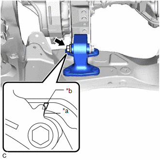
(c) Fully tighten the bolt of the front engine mounting insulator.
Torque:
87 N·m {887 kgf·cm, 64 ft·lbf}
14. INSTALL STEERING LINK ASSEMBLY
Click here
15. INSTALL FRONT NO. 1 STABILIZER BRACKET LH
Click here
16. INSTALL FRONT NO. 1 STABILIZER BRACKET RH
HINT:
Perform the same procedure as for the LH side.
17. INSTALL NO. 2 VACUUM SWITCHING VALVE ASSEMBLY
Click here
18. INSTALL ENGINE WIRE
(a) Connect all connectors and clamps, and install the engine wire to the engine assembly with transaxle.
19. INSTALL ENGINE ASSEMBLY WITH TRANSAXLE
HINT:
Perform "Inspection After Repair" after replacing the engine assembly.
Click here
(a) Using height adjustment attachments and plate lift attachments to keep the engine assembly with transaxle and front frame assembly level, set an engine lifter underneath the engine assembly with transaxle and front frame assembly.
NOTICE:
- Do not perform any procedures while the engine assembly is suspended because doing so may cause the engine assembly to drop, resulting in injury. However, the engine assembly needs to be suspended when it is installed to or removed from an engine stand.
- To prevent the engine assembly from unexpectedly moving, securely support the engine assembly until it is secured to an engine stand.
(b) Remove the 4 bolts, No. 1 engine hanger and No. 2 engine hanger.
(c) Operate the engine lifter and install the engine assembly with transaxle to the vehicle.
CAUTION:
Do not raise the engine assembly with transaxle more than necessary. If the engine is raised excessively, the vehicle may also be lifted up.
NOTICE:
- Make sure that the engine assembly with transaxle is clear of all wiring and hoses.
- While raising the engine assembly with transaxle into the vehicle, do not allow it to contact the vehicle.
(d) Install the frame side rail plate sub-assembly RH and frame side rail plate sub-assembly LH to the front frame assembly and vehicle body with the 6 bolts and 2 nuts.
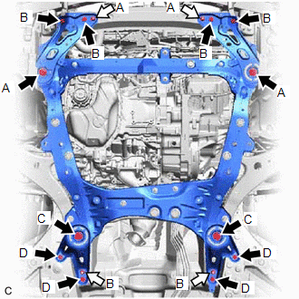
.png) | Bolt |
.png) | Nut |
Torque:
Bolt (A) :
85 N·m {867 kgf·cm, 63 ft·lbf}
Bolt (B) and Nut (A) :
32 N·m {326 kgf·cm, 24 ft·lbf}
(e) Install the front suspension member bracket sub-assembly RH and front suspension member bracket sub-assembly LH to the front frame assembly and vehicle body with the 6 bolts and 2 nuts.
Torque:
Bolt (C) :
85 N·m {867 kgf·cm, 63 ft·lbf}
Bolt (D) and Nut (B) :
32 N·m {326 kgf·cm, 24 ft·lbf}
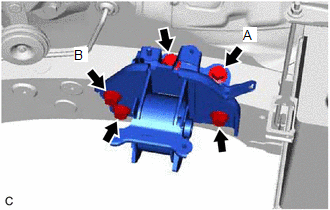
| (f) Install the engine mounting insulator sub-assembly RH to the front No. 1 engine mounting bracket LH with the 2 bolts and 2 nuts. Torque: Bolt and Nut (A) : 71 N·m {724 kgf·cm, 52 ft·lbf} Nut (B) : 40 N·m {408 kgf·cm, 30 ft·lbf} |
|
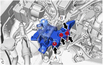
(g) Install the No. 2 engine mounting stay RH with the bolt and 2 nuts.
Torque:
20 N·m {204 kgf·cm, 15 ft·lbf}
(h) Install the engine mounting insulator LH to the engine mounting bracket LH with the bolt and nut.
Torque:
40 N·m {408 kgf·cm, 30 ft·lbf}
NOTICE:
Tighten the bolt while holding the nut in place.
20. INSTALL DRIVE PLATE AND TORQUE CONVERTER ASSEMBLY SETTING BOLT
for U881E: Click here
for U881F: Click here
21. INSTALL FLYWHEEL HOUSING UNDER COVER
for U881E: Click here
for U881F: Click here
22. INSTALL PROPELLER WITH CENTER BEARING SHAFT ASSEMBLY
Click here
23. INSTALL FRONT DRIVE SHAFT ASSEMBLY
Click here
24. CONNECT STEERING INTERMEDIATE SHAFT ASSEMBLY
Click here
25. INSTALL EXHAUST MANIFOLD
Click here
26. CONNECT SUCTION HOSE SUB-ASSEMBLY
Click here
27. CONNECT DISCHARGE HOSE SUB-ASSEMBLY
Click here
28. CONNECT NO. 1 TRANSMISSION OIL COOLER HOSE ASSEMBLY
Click here
29. CONNECT NO. 1 TRANSMISSION OIL COOLER HOSE ASSEMBLY
for U881E: Click here
for U881F: Click here
30. CONNECT UNION TO CHECK VALVE HOSE
Click here
31. CONNECT OUTLET HEATER WATER HOSE
(a) Connect the outlet heater water hose to the water inlet pipe and slide the clip to secure it.
32. CONNECT INLET HEATER WATER HOSE
(a) Connect the inlet heater water hose to the water outlet and slide the clip to secure it.
(b) Engage the clamp.
33. CONNECT NO. 2 RADIATOR HOSE
Click here
34. CONNECT NO. 1 RADIATOR HOSE
(a) Install the No. 1 radiator hose to the radiator pipe clamp.
(b) Connect the No. 1 radiator hose to the water outlet and slide the clip to secure it.
35. CONNECT NO. 1 FUEL HOSE
(a) Connect the fuel tube sub-assembly (for Port Injection).
(1) Connect the fuel tube sub-assembly to the fuel pipe.
Click here
(b) Connect the No. 2 fuel tube sub-assembly (for Direct Injection).
(1) Connect the No. 2 fuel tube sub-assembly to the fuel pipe.
Click here
(c) Install the No. 2 fuel pipe clamp to the fuel tube connector.
36. CONNECT FUEL VAPOR FEED HOSE ASSEMBLY
(a) Connect the fuel vapor feed hose assembly to the No. 1 vacuum switching valve and slide the clip to secure it.
37. CONNECT TRANSMISSION CONTROL CABLE ASSEMBLY
for U881E: Click here
for U881F: Click here
38. CONNECT ENGINE WIRE
(a) Connect the No. 2 earth wire to the bracket with the bolt.
Torque:
8.4 N·m {86 kgf·cm, 74 in·lbf}
(b) Engage the clamp and connect the engine wire to the vehicle body.
(c) Engage the 2 claws to connect the engine room main wire to the engine wire.
(d) Connect the engine room main wire with engine wire to the positive (+) battery terminal with the nut.
Torque:
7.6 N·m {77 kgf·cm, 67 in·lbf}
(e) Engage the clamp and connect the engine wire to the engine mounting insulator LH.
(f) Engage the claw and connect the engine wire to the engine room relay block assembly.
(g) Install the 2 nuts to the engine mounting insulator LH and vehicle body.
Torque:
8.4 N·m {86 kgf·cm, 74 in·lbf}
(h) Engage the clamp to the engine room relay block assembly.
(i) Connect the engine wire to the vehicle body with the bolt.
Torque:
8.4 N·m {86 kgf·cm, 74 in·lbf}
(j) Install the nut to the engine room relay block assembly.
Torque:
8.4 N·m {86 kgf·cm, 74 in·lbf}
(k) Connect the 3 connectors to the engine room relay block assembly.
(l) Install the No. 1 relay block cover to the engine room relay block assembly.
39. INSTALL ECM
Click here
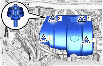
40. INSTALL V-BANK COVER SUB-ASSEMBLY
| (a) Engage the 4 clips in the order shown in the illustration to install the V-bank cover sub-assembly. NOTICE:
|
|
41. INSTALL AIR CLEANER BRACKET
(a) Install the air cleaner bracket to the engine mounting insulator LH with the 2 bolts.
Torque:
8.0 N·m {82 kgf·cm, 71 in·lbf}
(b) Engage the clamp.
42. INSTALL AIR CLEANER CASE SUB-ASSEMBLY
(a) Install the air cleaner case sub-assembly to the engine mounting insulator LH and air cleaner bracket with the 2 bolts.
Torque:
5.0 N·m {51 kgf·cm, 44 in·lbf}
43. INSTALL AIR CLEANER FILTER ELEMENT SUB-ASSEMBLY
(a) Install the air cleaner filter element sub-assembly to the air cleaner case sub-assembly.
44. INSTALL AIR CLEANER CAP WITH AIR CLEANER HOSE
Click here
45. INSTALL INLET AIR CLEANER ASSEMBLY
Click here
46. INSTALL COOL AIR INTAKE DUCT SEAL
Click here
47. CONNECT CABLE TO NEGATIVE BATTERY TERMINAL
-
for 180A Type:
Click here
-
for 150A Type:
Click here
48. ADD ENGINE OIL
Click here
49. ADD ENGINE COOLANT
Click here
50. CHARGE AIR CONDITIONING SYSTEM WITH REFRIGERANT
Click here
51. WARM UP ENGINE
Click here
52. INSPECT SHIFT LEVER POSITION
for U881E: Click here
for U881F: Click here
53. ADJUST SHIFT LEVER POSITION (for 2WD)
Click here
54. ADJUST SHIFT LEVER POSITION (for AWD)
for TMC Made: Click here
for TMMC Made: Click here
55. INSPECT FOR ENGINE OIL LEAK
Click here
56. INSPECT FOR COOLANT LEAK
Click here
57. INSPECT FOR AUTOMATIC TRANSAXLE FLUID LEAK
58. INSPECT FOR REFRIGERANT LEAK
Click here
59. INSPECT FOR FUEL LEAK
Click here
60. INSPECT FOR EXHAUST GAS LEAK
Click here
61. CHECK ENGINE OIL LEVEL
Click here
62. INSPECT ENGINE COOLANT LEVEL IN RESERVOIR TANK
Click here
63. INSTALL FRONT FENDER APRON SEAL RH
(a) Install the front fender apron seal RH to the vehicle body with the 2 bolts and clip.
64. INSTALL FRONT FENDER APRON SEAL LH
(a) Install the front fender apron seal LH to the vehicle body with the 2 bolts and clip.
65. INSTALL FRONT FLOOR COVER LH
Click here
66. INSTALL NO. 2 ENGINE UNDER COVER
(a) Install the No. 2 engine under cover to the front frame assembly with the 2 bolts, 2 screws and clip.
67. INSTALL SUSPENSION TOWER DAMPER (w/ Suspension Tower Damper)
Click here
68. INSTALL FRONT LOWER BUMPER ABSORBER
(a) Engage the 2 claws and install the front lower bumper absorber to the vehicle body with the 4 screws and 2 clips.
69. INSTALL NO. 1 ENGINE UNDER COVER
(a) Install the No. 1 engine under cover to the vehicle body with the 3 bolts, 2 screws and clip.
70. INSTALL FRONT WHEEL OPENING EXTENSION PAD RH
(a) Install the front wheel opening extension pad RH to the No. 1 engine under cover with the 2 screws.
71. INSTALL NO. 3 ENGINE UNDER COVER
(a) Install the No. 3 engine under cover to the vehicle body with the 5 bolts, 2 screws and 2 clips.
72. INSTALL FRONT WHEEL OPENING EXTENSION PAD LH
(a) Install the front wheel opening extension pad LH to the No. 3 engine under cover with the 2 screws.
73. ALIGN FRONT WHEELS FACING STRAIGHT AHEAD
Click here
74. INSPECT AND ADJUST FRONT WHEEL ALIGNMENT
Click here
75. PERFORM INITIALIZATION
Click here
76. INSPECT IGNITION TIMING
Click here
77. INSPECT ENGINE IDLE SPEED
Click here
78. INSPECT CO/HC
Click here
79. CHECK FOR SPEED SENSOR SIGNAL
Click here
 Components
COMPONENTS ILLUSTRATION *A for TMC Made *B for TMMC Made *1 NO. 1 ENGINE UNDER COVER *2 NO. 2 ENGINE UNDER COVER *3 NO. 3 ENGINE UNDER COVER *4 FRONT FENDER APRON SEAL LH ...
 Removal
REMOVAL CAUTION / NOTICE / HINT The necessary procedures (adjustment, calibration, initialization, or registration) that must be performed after parts are removed and installed, or replaced during eng ...
Other materials:
Lexus RX (RX 350L, RX450h) 2016-2026 Repair Manual > Navigation System: MOST Communication Malfunction (B15D0)
DESCRIPTION Navigation system components communicate with each other via MOST communication. If a line short or short to ground occurs in a MOST communication line, communication will not be possible and the navigation system will not operate normally. After the engine switch is turned on (ACC), if ...
Lexus RX (RX 350L, RX450h) 2016-2026 Repair Manual > Can Communication System: Open in One Side of Bus 1 Branch Line
DESCRIPTION If an ECU or sensor is not displayed on the CAN Bus Check screen of the Techstream and some ECUs and sensors repeatedly appear and disappear from the screen when the CAN main bus lines are normal (there is no open, short, short to +B or short to GND in the main bus lines), there may be a ...
Lexus RX (RX 350L, RX450h) 2016-{YEAR} Owners Manual
- For your information
- Pictorial index
- For safety and security
- Instrument cluster
- Operation of each component
- Driving
- Lexus Display Audio system
- Interior features
- Maintenance and care
- When trouble arises
- Vehicle specifications
- For owners
Lexus RX (RX 350L, RX450h) 2016-{YEAR} Repair Manual

0.0127