Lexus RX (RX 350L, RX450h) 2016-2026 Repair Manual: Installation
INSTALLATION
PROCEDURE
1. INSTALL FUEL INJECTOR ASSEMBLY
HINT:
Perform "Inspection After Repair" after replacing a fuel injector assembly.
Click here .gif)
(a) Apply a light coat of spindle oil or gasoline to 6 new O-rings, and install 1 to each fuel injector assembly.
NOTICE:
Check that there is no damage or foreign matter on the groove of the fuel injector assembly when installing the O-ring to each fuel injector assembly.
(b) for Bank 1:
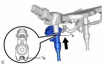
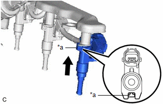
(1) Connect the 3 fuel injector assembly connectors.
| (2) Install the 3 fuel injector assemblies to the fuel delivery pipe sub-assembly. NOTICE:
|
|
(3) Engage the clamp to connect the No. 5 engine wire to the fuel delivery pipe sub-assembly.
(c) for Bank 2:
(1) Connect the 3 fuel injector assembly connectors.
| (2) Install the 3 fuel injector assemblies to the fuel delivery pipe sub-assembly. NOTICE:
|
|
(3) Engage the clamp to connect the No. 5 engine wire to the fuel delivery pipe sub-assembly.
2. INSTALL INJECTOR VIBRATION INSULATOR
(a) Install 6 new injector vibration insulators to the intake manifold.
3. INSTALL NO. 1 DELIVERY PIPE SPACER
(a) Install the 4 No. 1 delivery pipe spacers to the intake manifold.
4. INSTALL FUEL DELIVERY PIPE SUB-ASSEMBLY
(a) Place the fuel delivery pipe sub-assembly with the 6 fuel injector assemblies onto the intake manifold.
NOTICE:
Be careful not to drop the fuel injector assemblies when installing the fuel delivery pipe sub-assembly.
(b) Install the fuel delivery pipe sub-assembly with the fuel injector assemblies with the 4 bolts.
Torque:
17 N·m {173 kgf·cm, 13 ft·lbf}
(c) Connect the 2 No. 5 engine wire connectors.
(d) Connect the fuel pressure sensor connector.
5. CONNECT FUEL TUBE SUB-ASSEMBLY
(a) Connect the fuel tube sub-assembly to the fuel delivery pipe sub-assembly.
Click here
6. INSTALL INTAKE AIR SURGE TANK ASSEMBLY
Click here
7. CONNECT CABLE TO NEGATIVE BATTERY TERMINAL
NOTICE:
When disconnecting the cable, some systems need to be initialized after the cable is reconnected.
Click here
8. INSPECT FOR FUEL LEAK
Click here
9. PERFORM INITIALIZATION
(a) Perform "Inspection After Repair" after replacing a fuel injector assembly.
Click here
 Inspection
INSPECTION PROCEDURE 1. INSPECT FUEL INJECTOR ASSEMBLY (a) Check the resistance. (1) Measure the resistance according to the value(s) in the table below. Standard Resistance: Tester Connection ...
 Fuel Main Valve
...
Other materials:
Lexus RX (RX 350L, RX450h) 2016-2026 Repair Manual > Power Steering System: Parts Location
PARTS LOCATION ILLUSTRATION *A w/ Forward Recognition Camera System - - *1 ECM *2 BRAKE ACTUATOR ASSEMBLY - SKID CONTROL ECU *3 POWER STEERING ECU ASSEMBLY - POWER STEERING MOTOR *4 FORWARD RECOGNITION CAMERA *5 ELECTRIC POWER STEERING COLUMN SUB-ASSEMBLY - TORQUE ...
Lexus RX (RX 350L, RX450h) 2016-2026 Owners Manual > For safe use: Front passenger occupant
classification system
Your vehicle is equipped with a front passenger occupant classification
system.
This system detects the conditions of the front passenger seat and activates
or deactivates the devices for the front passenger.
SRS warning light
Seat belt reminder light
"AIR BAG OFF" indicator light
...
Lexus RX (RX 350L, RX450h) 2016-{YEAR} Owners Manual
- For your information
- Pictorial index
- For safety and security
- Instrument cluster
- Operation of each component
- Driving
- Lexus Display Audio system
- Interior features
- Maintenance and care
- When trouble arises
- Vehicle specifications
- For owners
Lexus RX (RX 350L, RX450h) 2016-{YEAR} Repair Manual

0.0134