Lexus RX (RX 350L, RX450h) 2016-2026 Repair Manual: Inspection
INSPECTION
PROCEDURE
1. INSPECT FUEL INJECTOR ASSEMBLY
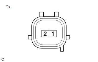
(a) Check the resistance.
| (1) Measure the resistance according to the value(s) in the table below. Standard Resistance:
If the result is not as specified, replace the fuel injector assembly. |
|
(b) Check the operation.
CAUTION:
Perform the inspection in a well-ventilated area.
Do not perform the inspection near an open flame.
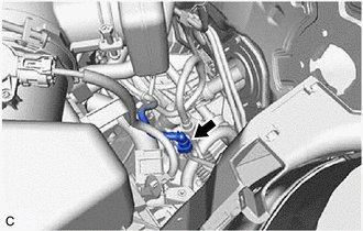
| (1) Remove the No. 2 fuel pipe clamp from the fuel tube connector. |
|
.png)
| (2) Disconnect the fuel tube sub-assembly. Click here |
|
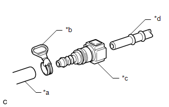
| (3) Connect SST (fuel tube connector) to SST (hose) with SST (hose band), and then connect them to the fuel pipe (vehicle side). SST: 09268-31015 09268-41500 09268-41700 95336-08070 NOTICE: Make sure the SST (fuel tube connector) O-rings are not damaged and are free of foreign matter as they are used to seal the connections between the fuel tube connector and fuel pipe. |
|
(4) Apply a light coat of gasoline to a new O-ring, and then install the O-ring to the fuel injector assembly.
| (5) Connect SST (adapter) and SST (hose) to the fuel injector assembly, and hold the fuel injector assembly and union with SST (clamp). SST: 09268-31015 09268-41600 09268-41300 09268-41700 95336-08070 |
|
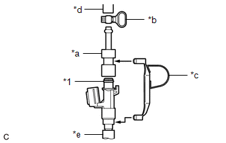
| (6) Tie SST (clamp) and SST (adapter) together with SST (tie band) as shown in the illustration. SST: 09268-31015 09268-41800 NOTICE:
HINT: When removing SST (tie band), disengage the lock. |
|
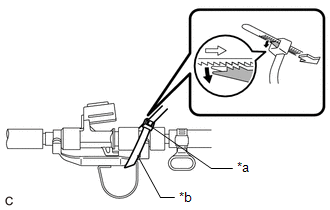
(7) Check that SST (clamp) and SST (adapter) cannot be easily separated.
(8) Install a vinyl tube to the fuel injector assembly.
CAUTION:
Install a suitable vinyl tube to the fuel injector assembly to prevent fuel from spraying.
(9) Set the fuel injector assembly into a graduated cylinder.
(10) Operate the fuel pump.
Click here .gif)
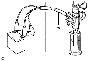
| (11) Connect SST (EFI inspection wire I) to the fuel injector assembly and battery for 15 seconds, and measure the injection volume with the graduated cylinder. Test each fuel injector assembly 2 or 3 times. SST: 09842-30090 Standard Injection Volume:
Difference between Each Fuel Injector Assembly: 14 cc (0.9 cu. in.) or less NOTICE:
If the injection volume is not as specified, replace the fuel injector assembly. |
|
(c) Check for leaks.
(1) Disconnect SST (EFI inspection wire I) from the battery and check for fuel leaks from the fuel injector assembly.
Standard Fuel Drop:
1 drop or less per 20 minutes
If the result is not as specified, replace the fuel injector assembly.
(2) Connect the fuel tube sub-assembly.
Click here
(3) Install the No. 2 fuel pipe clamp to the fuel tube connector.
(4) Check for fuel leaks.
Click here
 Removal
REMOVAL CAUTION / NOTICE / HINT The necessary procedures (adjustment, calibration, initialization or registration) that must be performed after parts are removed and installed, or replaced during fuel ...
 Installation
INSTALLATION PROCEDURE 1. INSTALL FUEL INJECTOR ASSEMBLY HINT: Perform "Inspection After Repair" after replacing a fuel injector assembly. Click here (a) Apply a light coat of spindle oil or gasoli ...
Other materials:
Lexus RX (RX 350L, RX450h) 2016-2026 Repair Manual > Airbag System: Short in Passenger Side Front Seat Cushion Squib Circuit (B1875-B1878)
DESCRIPTION The passenger side front seat cushion squib circuit consists of the airbag sensor assembly and front seat cushion airbag assembly RH. The airbag sensor assembly uses this circuit to deploy the airbag when deployment conditions are met. These DTCs are stored when a malfunction is detected ...
Lexus RX (RX 350L, RX450h) 2016-2026 Repair Manual > Seat Belt Warning System: On-vehicle Inspection
ON-VEHICLE INSPECTION PROCEDURE 1. INSPECT DRIVER SEAT BELT WARNING LIGHT HINT: The seat belt warning light on the combination meter assembly is used for both the driver seat and front passenger seat. (a) Turn the engine switch on (IG). (b) When the driver seat belt is not fastened, check that the s ...
Lexus RX (RX 350L, RX450h) 2016-{YEAR} Owners Manual
- For your information
- Pictorial index
- For safety and security
- Instrument cluster
- Operation of each component
- Driving
- Lexus Display Audio system
- Interior features
- Maintenance and care
- When trouble arises
- Vehicle specifications
- For owners
Lexus RX (RX 350L, RX450h) 2016-{YEAR} Repair Manual

0.0487