Lexus RX (RX 350L, RX450h) 2016-2026 Repair Manual: Removal
REMOVAL
CAUTION / NOTICE / HINT
The necessary procedures (adjustment, calibration, initialization or registration) that must be performed after parts are removed and installed, or replaced during fuel injector assembly removal/installation are shown below.
Necessary Procedures After Parts Removed/Installed/Replaced| Replaced Part or Performed Procedure | Necessary Procedure | Effect/Inoperative Function when Necessary Procedure not Performed | Link |
|---|---|---|---|
|
*1: When performing learning using the Techstream.
Click here | |||
| Battery terminal is disconnected/reconnected | Memorize steering angle neutral point | Lane Control System | |
| Pre-collision system | |||
| Intelligent clearance sonar system*1 | |||
| Lighting system (w/ Automatic Headlight Beam Level Control System) | | ||
| Parking assist monitor system | | ||
| Panoramic view monitor system | | ||
| Initialize back door lock | Power door lock control system | | |
| Reset back door close position | Power Back Door System (w/ Outside Door Control Switch) | | |
| Inspection After Repair |
| |
PROCEDURE
1. PRECAUTION
NOTICE:
After turning the engine switch off, waiting time may be required before disconnecting the cable from the negative (-) battery terminal. Therefore, make sure to read the disconnecting the cable from the negative (-) battery terminal notices before proceeding with work.
Click here .gif)
2. DISCHARGE FUEL SYSTEM PRESSURE
Click here
3. DISCONNECT CABLE FROM NEGATIVE BATTERY TERMINAL
NOTICE:
When disconnecting the cable, some systems need to be initialized after the cable is reconnected.
Click here
4. REMOVE INTAKE AIR SURGE TANK ASSEMBLY
Click here
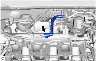
5. DISCONNECT FUEL TUBE SUB-ASSEMBLY
| (a) Disconnect the fuel tube sub-assembly from the fuel delivery pipe sub-assembly. Click here |
|
6. REMOVE FUEL DELIVERY PIPE SUB-ASSEMBLY
| (a) Disconnect the fuel pressure sensor connector. |
|
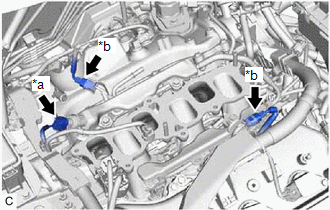
(b) Disconnect the 2 No. 5 engine wire connectors.
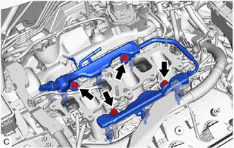
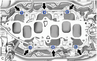
| (c) Remove the 4 bolts and fuel delivery pipe sub-assembly with the 6 fuel injector assemblies from the intake manifold. NOTICE:
|
|
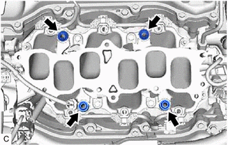
7. REMOVE NO. 1 DELIVERY PIPE SPACER
| (a) Remove the 4 No. 1 delivery pipe spacers from the intake manifold. |
|
8. REMOVE INJECTOR VIBRATION INSULATOR
| (a) Remove the 6 injector vibration insulators from the intake manifold. |
|
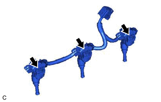
9. REMOVE FUEL INJECTOR ASSEMBLY
(a) for Bank 2:
| (1) Disengage the clamp to disconnect the No. 5 engine wire from the fuel delivery pipe sub-assembly. |
|
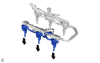
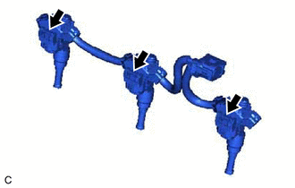
(2) Pull the 3 fuel injector assemblies out of the fuel delivery pipe sub-assembly.
| (3) Disconnect the 3 fuel injector assembly connectors. |
|
(b) for Bank 1:
| (1) Disengage the clamp to disconnect the No. 5 engine wire from the fuel delivery pipe sub-assembly. |
|
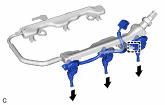
(2) Pull the 3 fuel injector assemblies out of the fuel delivery pipe sub-assembly.
| (3) Disconnect the 3 fuel injector assembly connectors. |
|
(c) Remove the O-ring from each fuel injector assembly.
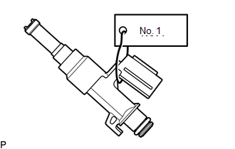
| (d) Attach a tag or label with the corresponding cylinder number to each fuel injector assembly so that they can be installed to their original locations. NOTICE: Cover the fuel injector assemblies with plastic bags to prevent damage and contamination. |
|
 Components
COMPONENTS ILLUSTRATION *1 FUEL DELIVERY PIPE SUB-ASSEMBLY *2 FUEL INJECTOR ASSEMBLY *3 FUEL TUBE SUB-ASSEMBLY *4 INJECTOR VIBRATION INSULATOR *5 NO. 1 DELIVERY PIPE SPACER ...
 Inspection
INSPECTION PROCEDURE 1. INSPECT FUEL INJECTOR ASSEMBLY (a) Check the resistance. (1) Measure the resistance according to the value(s) in the table below. Standard Resistance: Tester Connection ...
Other materials:
Lexus RX (RX 350L, RX450h) 2016-2026 Repair Manual > Blower Unit: Installation
INSTALLATION PROCEDURE 1. INSTALL CLEAN AIR FILTER (a) Engage the 4 guides as indicated by the arrows, in the order shown in the illustration to install the clean air filter to the air filter case. Install in this Direction (1) Install in this Direction (2) NOTICE: Make sure that the ...
Lexus RX (RX 350L, RX450h) 2016-2026 Repair Manual > Back Door Outside Garnish: Installation
INSTALLATION PROCEDURE 1. INSTALL NO. 1 BACK DOOR NAME PLATE (a) Engage the 2 guides and 4 claws to install the No. 1 back door name plate. 2. INSTALL BACK DOOR OUTSIDE GARNISH SUB-ASSEMBLY (a) Pull back the lower back window moulding and secure it with tape as shown in the illustration. *1 Lo ...
Lexus RX (RX 350L, RX450h) 2016-{YEAR} Owners Manual
- For your information
- Pictorial index
- For safety and security
- Instrument cluster
- Operation of each component
- Driving
- Lexus Display Audio system
- Interior features
- Maintenance and care
- When trouble arises
- Vehicle specifications
- For owners
Lexus RX (RX 350L, RX450h) 2016-{YEAR} Repair Manual

0.0098