Lexus RX (RX 350L, RX450h) 2016-2026 Repair Manual: System Diagram
SYSTEM DIAGRAM
FUEL FLOW DIAGRAM
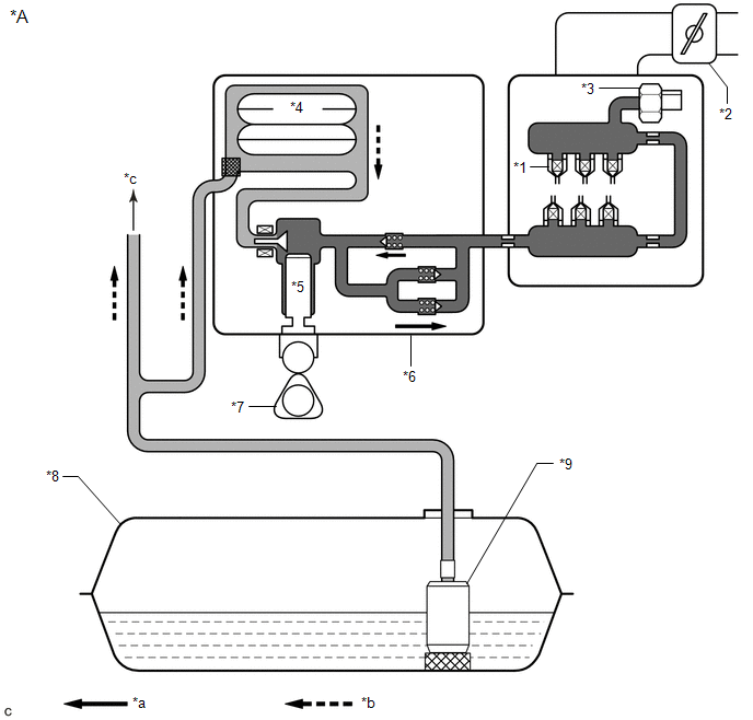
| *A | for Direct Injection | - | - |
| *1 | Fuel Injector Assembly | *2 | Throttle Body with Motor Assembly |
| *3 | Fuel Pressure Sensor (for High Pressure) | *4 | Fuel Pressure Pulsation Damper Assembly |
| *5 | Plunger | *6 | Fuel Pump Assembly (for High Pressure) |
| *7 | Camshaft | *8 | Fuel Tank Assembly |
| *9 | Fuel Suction Tube with Pump and Gauge Assembly - Fuel Sender Gauge Assembly - Fuel Main Valve Assembly - Fuel Pump (for Low Pressure) | - | - |
| *a | High Pressure Fuel Line | *b | Low Pressure Fuel Line |
| *c | To Fuel Injector Assembly (for Port Injection) | - | - |
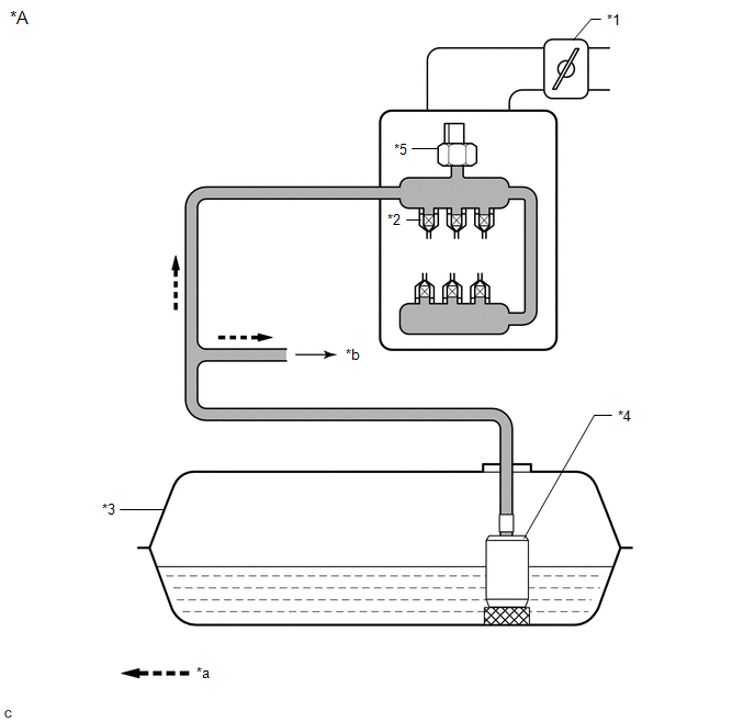
| *A | for Port Injection | - | - |
| *1 | Throttle Body with Motor Assembly | *2 | Fuel Injector Assembly |
| *3 | Fuel Tank Assembly | *4 | Fuel Suction Tube with Pump and Gauge Assembly - Fuel Sender Gauge Assembly - Fuel Main Valve Assembly - Fuel Pump (Low Pressure) |
| *5 | Fuel Pressure Sensor (for Low Pressure) | - | - |
| *a | Low Pressure Fuel Line | *b | To Fuel Pump Assembly (for High Pressure) |
ELECTRICAL CONTROL DIAGRAM
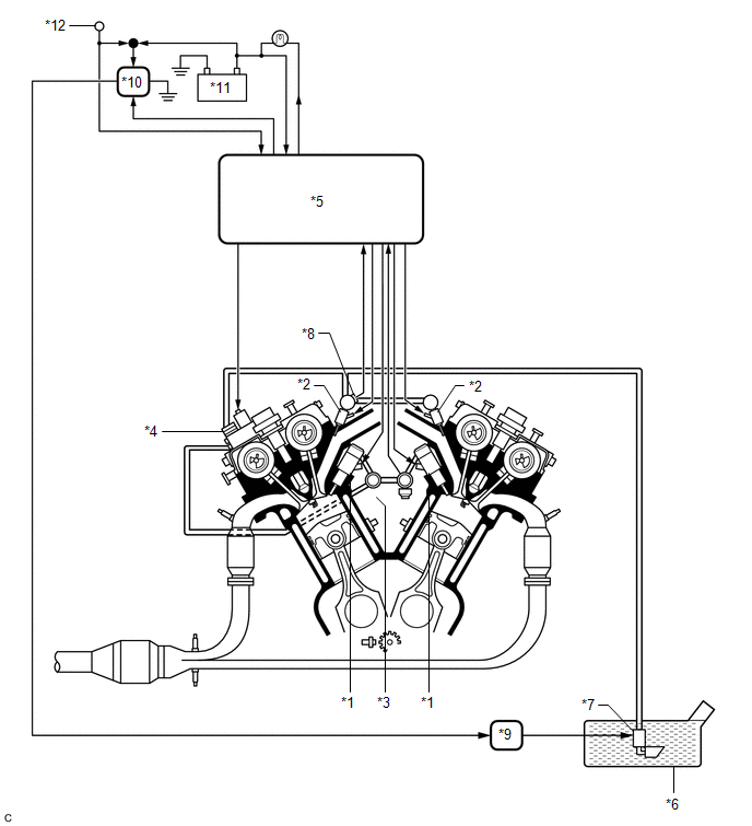
| *1 | Fuel Injector Assembly (for Direct Injection) | *2 | Fuel Injector Assembly (for Port Injection) |
| *3 | Fuel Pressure Sensor (for High Pressure) | *4 | Fuel Pump Assembly (for High Pressure) |
| *5 | ECM | *6 | Fuel Tank Assembly |
| *7 | Fuel Pump (Low Pressure) | *8 | Fuel Pressure Sensor (for Low Pressure) |
| *9 | Fuel Pump Control ECU Assembly | *10 | C/OPN Relay |
| *11 | Battery | *12 | Engine Switch |
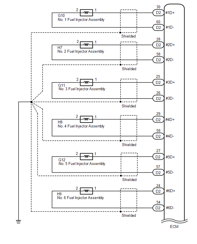
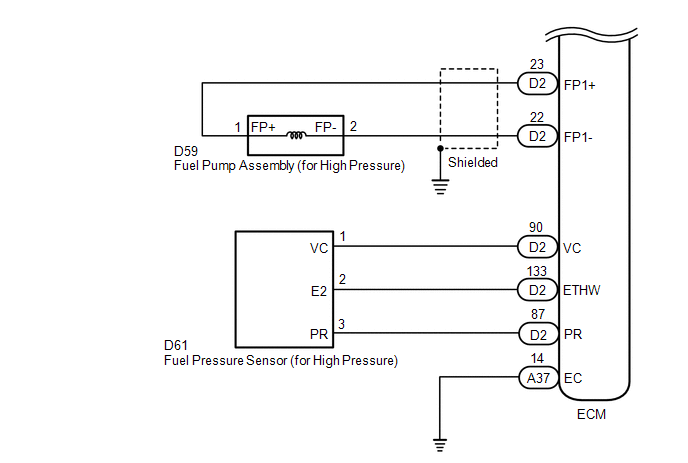
HIGH PRESSURE SIDE FUEL SYSTEM WIRING DIAGRAM
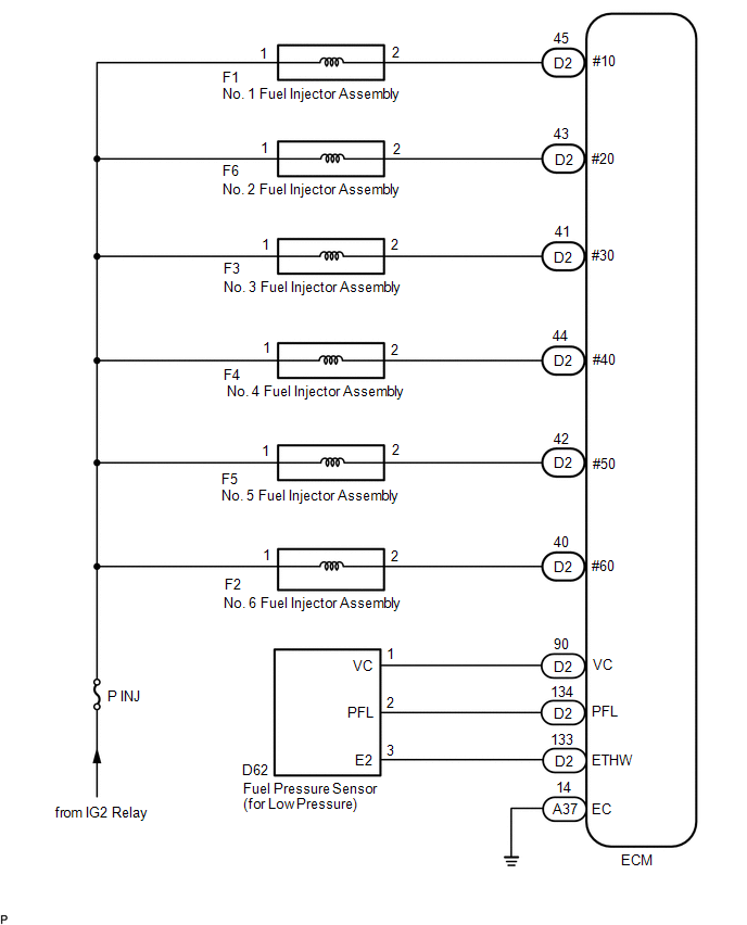
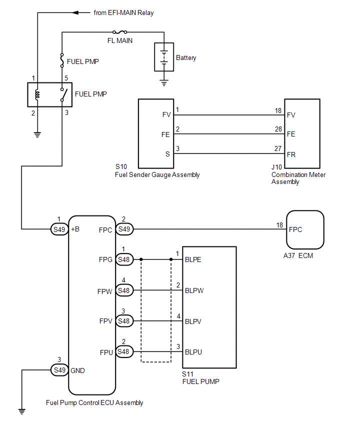
LOW PRESSURE SIDE FUEL SYSTEM WIRING DIAGRAM
 Precaution
PRECAUTION CAUTION:
The fuel tank assembly is very heavy. Be sure to follow the procedure described in the repair manual, or the fuel tank assembly may fall off the engine lifter.
To prevent ser ...
 On-vehicle Inspection
ON-VEHICLE INSPECTION PROCEDURE 1. CHECK FUEL PUMP OPERATION AND INSPECT FOR FUEL LEAK (a) Check fuel pump operation. (1) Connect the Techstream to the DLC3. (2) Turn the engine switch on (IG). NOTICE ...
Other materials:
Lexus RX (RX 350L, RX450h) 2016-2026 Repair Manual > Cylinder Block: Replacement
REPLACEMENT PROCEDURE 1. REPLACE STRAIGHT PIN NOTICE: If a straight pin is deformed, replace it. (a) Using a plastic hammer, tap in new straight pins to the cylinder block sub-assembly. *a Front Side *b Rear Side *c Top Side *d Bottom Side *e RH Side *f 23 mm (0.906 in. ...
Lexus RX (RX 350L, RX450h) 2016-2026 Repair Manual > Audio And Visual System (for 8 Inch Display): Panel Switches do not Function
CAUTION / NOTICE / HINT NOTICE: Depending on the parts that are replaced during vehicle inspection or maintenance, performing initialization, registration or calibration may be needed. Refer to Precaution for Audio and Visual System. Click here PROCEDURE 1. CHECK PANEL SWITCH (a) Check fo ...
Lexus RX (RX 350L, RX450h) 2016-{YEAR} Owners Manual
- For your information
- Pictorial index
- For safety and security
- Instrument cluster
- Operation of each component
- Driving
- Lexus Display Audio system
- Interior features
- Maintenance and care
- When trouble arises
- Vehicle specifications
- For owners
Lexus RX (RX 350L, RX450h) 2016-{YEAR} Repair Manual

0.0102