Lexus RX (RX 350L, RX450h) 2016-2026 Repair Manual: Removal
REMOVAL
CAUTION / NOTICE / HINT
The necessary procedures (adjustment, calibration, initialization or registration) that must be performed after parts are removed and installed, or replaced during generator assembly removal/installation are shown below.
Necessary Procedures After Parts Removed/Installed/Replaced| Replaced Part or Performed Procedure | Necessary Procedure | Effect/Inoperative Function when Necessary Procedure not Performed | Link |
|---|---|---|---|
| Battery terminal is disconnected/reconnected | Memorize steering angle neutral point | Lane Control System | |
| Pre-collision system | |||
| Intelligent clearance sonar system*1 | |||
| Parking assist monitor system | | ||
| Panoramic view monitor system | | ||
| Lighting system (w/ Automatic Headlight Beam Level Control System) | | ||
| Initialize back door lock | Power door lock control system | | |
| Reset back door close position | Power Back Door System (w/ Outside Door Control Switch) | |
*1: When performing learning using the Techstream.
Click here .gif)
PROCEDURE
1. PRECAUTION
NOTICE:
After turning the engine switch off, waiting time may be required before disconnecting the cable from the negative (-) battery terminal. Therefore, make sure to read the disconnecting the cable from the negative (-) battery terminal notices before proceeding with work.
Click here
2. DISCONNECT CABLE FROM NEGATIVE BATTERY TERMINAL
NOTICE:
When disconnecting the cable, some systems need to be initialized after the cable is reconnected.
Click here
3. REMOVE RADIATOR ASSEMBLY
Click here
4. REMOVE V-RIBBED BELT
Click here
5. REMOVE GENERATOR ASSEMBLY
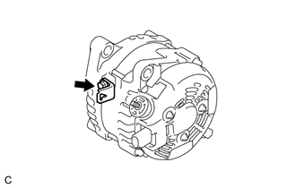
| (a) Open the terminal cap. |
|
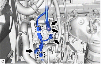
(b) Remove the nut and disconnect the wire harness from terminal B.
(c) Disconnect the generator assembly connector.
(d) Disconnect the compressor and magnetic clutch connector.
(e) Disengage the 2 wire harness clamps.
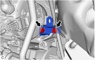
| (f) Type A: (1) Remove the 2 bolts and generator assembly bracket. |
|
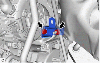
(g) Type B:
| (1) Remove the bolt, nut and generator assembly bracket. |
|
| (h) Remove the 2 bolts and generator assembly. |
|
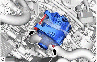
| (i) Remove the bolt and wire harness clamp bracket. |
|
 Components
COMPONENTS ILLUSTRATION *A Type A *B Type B *1 GENERATOR ASSEMBLY *2 WIRE HARNESS CLAMP BRACKET *3 TERMINAL CAP *4 GENERATOR ASSEMBLY BRACKET N*m (kgf*cm, ft.*lbf) ...
 Disassembly
DISASSEMBLY PROCEDURE 1. REMOVE GENERATOR PULLEY CAP (a) Using a screwdriver, remove the generator pulley cap from the generator pulley with clutch. NOTICE: Do not reuse the generator pulley cap. ...
Other materials:
Lexus RX (RX 350L, RX450h) 2016-2026 Repair Manual > Front Door Speaker: Components
COMPONENTS ILLUSTRATION *A for Driver Side *B for Front Passenger Side *1 COURTESY LIGHT ASSEMBLY *2 DOOR ARMREST COVER *3 FRONT DOOR INSIDE HANDLE BEZEL PLUG *4 FRONT DOOR NO. 1 STIFFENER CUSHION *5 FRONT DOOR TRIM BOARD SUB-ASSEMBLY *6 FRONT NO. 1 SPEAKER AS ...
Lexus RX (RX 350L, RX450h) 2016-2026 Repair Manual > Audio And Visual System (for 12.3 Inch Display): AVC-LAN Circuit
DESCRIPTION Each unit of the audio and visual system connected to the AVC-LAN (communication bus) transmits switch signals via AVC-LAN communication. If a short to +B or short to ground occurs in the AVC-LAN, the audio and visual system will not function normally because communication is not possibl ...
Lexus RX (RX 350L, RX450h) 2016-{YEAR} Owners Manual
- For your information
- Pictorial index
- For safety and security
- Instrument cluster
- Operation of each component
- Driving
- Lexus Display Audio system
- Interior features
- Maintenance and care
- When trouble arises
- Vehicle specifications
- For owners
Lexus RX (RX 350L, RX450h) 2016-{YEAR} Repair Manual

0.009