Lexus RX (RX 350L, RX450h) 2016-2026 Repair Manual: Front Recognition Camera Heater Malfunction (C1AAE00)
DESCRIPTION
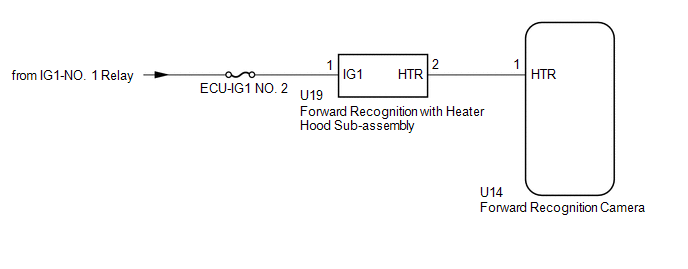
The forward recognition camera controls the flow of current to the forward recognition with heater hood sub-assembly.
If the forward recognition camera detects a malfunction in the forward recognition with heater hood sub-assembly circuit, it will store this DTC.
| DTC No. | Detection Item | DTC Detection Condition | Trouble Area |
|---|---|---|---|
| C1AAE00 | Front Recognition Camera Heater Malfunction | Either of the following conditions is met after 10 seconds have elapsed since the engine switch was turned to on (IG):
|
|
WIRING DIAGRAM
CAUTION / NOTICE / HINT
NOTICE:
- Inspect the fuses for circuits related to this system before performing the following procedure.
- When replacing the forward recognition camera, always replace it with a new one. If a forward recognition camera which was installed to another vehicle is used, the information stored in the forward recognition camera will not match the information from the vehicle. As a result, a DTC may be stored.
-
If the forward recognition camera has been replaced with a new one, be sure to perform forward recognition camera adjustment.
HINT:
Forward recognition camera adjustment can be performed by using either One Time Recognition or Sequential Recognition.
One Time Recognition: Click here
.gif)
Sequential Recognition: Click here
PROCEDURE
| 1. | CHECK FOR DTCs |
(a) Clear the DTCs.
Chassis > Front Recognition Camera > Clear DTCs(b) Make sure that the DTC detection conditions are met.
HINT:
If the detection conditions are not met, the system cannot detect the malfunction.
(c) Check for DTCs.
Chassis > Front Recognition Camera > Trouble Codes| Result | Proceed to |
|---|---|
| DTC C1AAE00 is not output | A |
| DTC C1AAE00 is output | B |
| A | .gif) | USE SIMULATION METHOD TO CHECK |
|
.gif)
| 2. | INSPECT FORWARD RECOGNITION WITH HEATER HOOD SUB-ASSEMBLY |
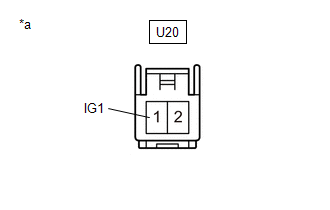
| *a | Component without harness connected (Forward Recognition with Heater Hood Sub-assembly) |
(a) Disconnect the U20 forward recognition with heater hood sub-assembly connector.
(b) Measure the resistance according to the value(s) in the table below.
Standard Resistance:
| Tester Connection | Condition | Specified Condition |
|---|---|---|
| 1 (IG1) - 2 (HTR) | Engine switch off | 28.5 to 31.5 Ω |
| NG | | REPLACE FORWARD RECOGNITION WITH HEATER HOOD SUB-ASSEMBLY |
|
| 3. | CHECK HARNESS AND CONNECTOR (POWER SOURCE VOLTAGE) |
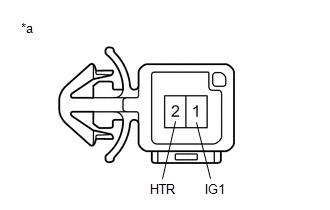
| *a | Front view of wire harness connector (to Forward Recognition with Heater Hood Sub-assembly) |
(a) Measure the voltage according to the value(s) in the table below.
Standard Voltage:
| Tester Connection | Condition | Specified Condition |
|---|---|---|
| U20-1 (IG1) - Body ground | Engine switch on (IG) | 8 to 16 V |
| Engine switch off | Below 1.5 V |
| NG | | REPAIR OR REPLACE HARNESS OR CONNECTOR |
|
| 4. | CHECK HARNESS AND CONNECTOR (FORWARD RECOGNITION WITH HEATER HOOD SUB-ASSEMBLY - FORWARD RECOGNITION CAMERA) |
(a) Disconnect the U14 forward recognition camera connector.
(b) Measure the resistance according to the value(s) in the table below.
Standard Resistance:
| Tester Connection | Condition | Specified Condition |
|---|---|---|
| U20-2 (HTR) - U14-1 (HTR) | Always | Below 1 Ω |
| U20-2 (HTR) or U14-1 (HTR) - Body ground | Always | 10 kΩ or higher |
| OK | | REPLACE FORWARD RECOGNITION CAMERA |
| NG | | REPAIR OR REPLACE HARNESS OR CONNECTOR |
 Front Recognition Camera Optical Axis Misalignment Malfunction (C1AA800)
DESCRIPTION The forward recognition camera monitors its optical axis status. If it determines that the optical axis alignment has become misaligned, it will store DTC C1AA800. DTC No. Detection I ...
 Lost Communication with ECM/PCM "A" Missing Message (U010087,U012587,U012687,U012987,U014087)
DESCRIPTION When a malfunction is detected between various ECUs and sensors, these DTCs are stored. DTC No. Detection Item DTC Detection Condition Trouble Area U010087 Lost Communicatio ...
Other materials:
Lexus RX (RX 350L, RX450h) 2016-2026 Repair Manual > Front Radar Sensor System: Diagnostic Trouble Code Chart
DIAGNOSTIC TROUBLE CODE CHART Front Radar Sensor System DTC No. Detection Item Link C1A1100 Front Radar Sensor Optical Axis Misalignment Malfunction C1A8C46 Main Microcomputer in Front Radar Sensor Calibration/Parameter Memory Failure C1A8D1C Power Supply Circuit i ...
Lexus RX (RX 350L, RX450h) 2016-2026 Repair Manual > Lighting System (w/o Automatic Headlight Beam Level Control System): Light Sensor Circuit (B1244)
DESCRIPTION The automatic light control sensor detects ambient light. The sensor creates an electrical signal based on the amount of light detected, and sends the signal to the main body ECU (multiplex network body ECU). The main body ECU (multiplex network body ECU) turns on or off the headlights a ...
Lexus RX (RX 350L, RX450h) 2016-{YEAR} Owners Manual
- For your information
- Pictorial index
- For safety and security
- Instrument cluster
- Operation of each component
- Driving
- Lexus Display Audio system
- Interior features
- Maintenance and care
- When trouble arises
- Vehicle specifications
- For owners
Lexus RX (RX 350L, RX450h) 2016-{YEAR} Repair Manual

0.0099