Lexus RX (RX 350L, RX450h) 2016-2026 Repair Manual: Steering Pad Switch Circuit
DESCRIPTION
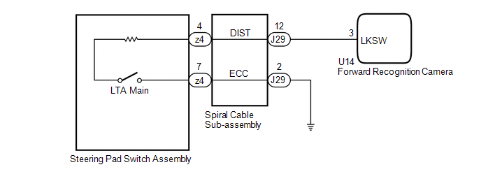
The forward recognition camera receives LTA main switch signals from the steering pad switch assembly.
WIRING DIAGRAM
CAUTION / NOTICE / HINT
NOTICE:
The vehicle is equipped with a Supplemental Restraint System (SRS) which includes components such as airbags. Before servicing (including removal or installation of parts), be sure to read the precaution for Supplemental Restraint System.
Click here .gif)
PROCEDURE
| 1. | INSPECT STEERING PAD SWITCH ASSEMBLY |
(a) Remove the steering pad switch assembly.
Click here
(b) Inspect the steering pad switch assembly.
Click here
| NG | .gif) | REPLACE STEERING PAD SWITCH ASSEMBLY |
|
.gif)
| 2. | INSPECT SPIRAL CABLE SUB-ASSEMBLY |
(a) Remove the spiral cable sub-assembly.
Click here
(b) Inspect the spiral cable sub-assembly.
Click here
| NG | | REPLACE SPIRAL CABLE SUB-ASSEMBLY |
|
| 3. | CHECK HARNESS AND CONNECTOR (SPIRAL CABLE SUB-ASSEMBLY - FORWARD RECOGNITION CAMERA) |
(a) Disconnect the U14 forward recognition camera connector.
(b) Measure the resistance according to the value(s) in the table below.
Standard Resistance:
| Tester Connection | Condition | Specified Condition |
|---|---|---|
| J29-12 (DIST) - U14-3 (LKSW) | Always | Below 1 Ω |
| J29-12 (DIST) or U14-3 (LKSW) - Body ground | Always | 10 kΩ or higher |
| NG | | REPAIR OR REPLACE HARNESS OR CONNECTOR |
|
| 4. | CHECK HARNESS AND CONNECTOR (SPIRAL CABLE SUB-ASSEMBLY - BODY GROUND) |
(a) Measure the resistance according to the value(s) in the table below.
Standard Resistance:
| Tester Connection | Condition | Specified Condition |
|---|---|---|
| J29-2 (ECC) - Body ground | Always | Below 1 Ω |
| OK | | PROCEED TO NEXT SUSPECTED AREA SHOWN IN PROBLEM SYMPTOMS TABLE |
| NG | | REPAIR OR REPLACE HARNESS OR CONNECTOR |
 Internal Control Module Software Incompatibility Invalid / Incompatible Software Component (U030057)
DESCRIPTION The forward recognition camera receives the vehicle information from the ECM via CAN communication. If the vehicle information stored in the forward recognition camera does not match the v ...
 Indicator Circuit
DESCRIPTION The forward recognition camera sends indicator illumination request signals to the combination meter assembly via CAN communication. CAUTION / NOTICE / HINT NOTICE:
When replacing the f ...
Other materials:
Lexus RX (RX 350L, RX450h) 2016-2026 Repair Manual > Dynamic Torque Control Awd System: Fail-safe Chart
FAIL-SAFE CHART FAIL-SAFE FUNCTION
If a malfunction is detected in the 4WD ECU assembly, the 4WD ECU assembly may stop AWD control and transfer all torque to the front wheels, or function in a such a way as to prevent damage to the system.
If a malfunction is detected in the sensor or actuator, ...
Lexus RX (RX 350L, RX450h) 2016-2026 Repair Manual > Starter: Inspection
INSPECTION PROCEDURE 1. INSPECT STARTER ASSEMBLY CAUTION: As a large electric current passes through the cable during this inspection, a thick cable must be used. If not, the cable may become hot and cause injury. NOTICE: Perform each of the following tests within 3 to 5 seconds to prevent the coil ...
Lexus RX (RX 350L, RX450h) 2016-{YEAR} Owners Manual
- For your information
- Pictorial index
- For safety and security
- Instrument cluster
- Operation of each component
- Driving
- Lexus Display Audio system
- Interior features
- Maintenance and care
- When trouble arises
- Vehicle specifications
- For owners
Lexus RX (RX 350L, RX450h) 2016-{YEAR} Repair Manual

0.0101