Lexus RX (RX 350L, RX450h) 2016-2026 Repair Manual: Certification ECU Communication Stop Mode
DESCRIPTION
| Detection Item | Symptom | Trouble Area |
|---|---|---|
| Certification ECU Communication Stop Mode | Either condition is met:
|
|
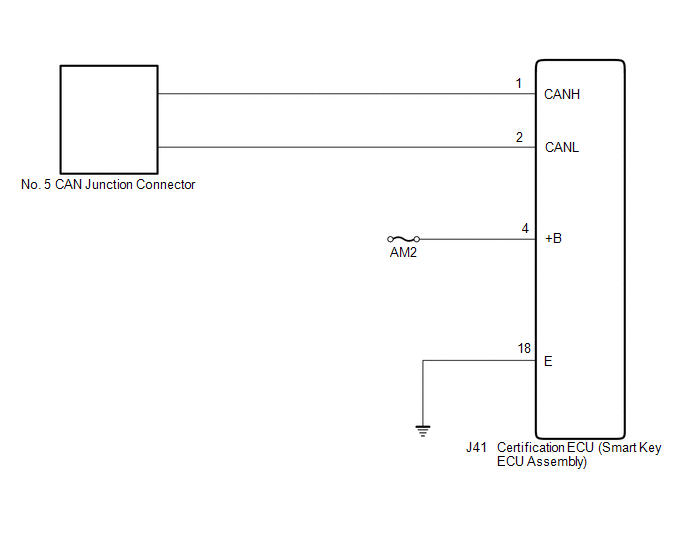
WIRING DIAGRAM
CAUTION / NOTICE / HINT
NOTICE:
- Before measuring the resistance of the CAN bus, turn the engine switch off and leave the vehicle for 1 minute or more without operating the key or any switches, or opening or closing the doors. After that, disconnect the cable from the negative (-) battery terminal and leave the vehicle for 1 minute or more before measuring the resistance.
-
After turning the engine switch off, waiting time may be required before disconnecting the cable from the negative (-) battery terminal. Therefore, make sure to read the disconnecting the cable from the negative (-) battery terminal notices before proceeding with work.
Click here
.gif)
-
Because the order of diagnosis is important to allow correct diagnosis, make sure to begin troubleshooting using How to Proceed with Troubleshooting when CAN communication system related DTCs are output.
Click here
- After performing repairs, perform the DTC check procedure and confirm that the DTCs are not output again.
- DTC check procedure: Turn the engine switch on (IG) and wait for at least 20 seconds.
-
After the repair, perform the CAN bus check and check that all the ECUs and sensors connected to the CAN communication system are displayed.
Click here
- Inspect the fuses for circuits related to this system before performing the following procedure.
-
Before replacing the certification ECU (smart key ECU assembly), refer to the smart access system with push-button start (for Start Function) Precaution.
Click here
HINT:
- Operating the engine switch, any other switches or a door triggers related ECU and sensor communication on the CAN. This communication will cause the resistance value to change.
- Even after DTCs are cleared, if a DTC is stored again after driving the vehicle for a while, the malfunction may be occurring due to vibration of the vehicle. In such a case, wiggling the ECUs or wire harness while performing the inspection below may help determine the cause of the malfunction.
PROCEDURE
| 1. | CHECK FOR OPEN IN CAN BUS LINES (CERTIFICATION ECU (SMART KEY ECU ASSEMBLY) BRANCH LINE) |
(a) Disconnect the cable from the negative (-) battery terminal.
| (b) Disconnect the J41 certification ECU (smart key ECU assembly) connector. |
|
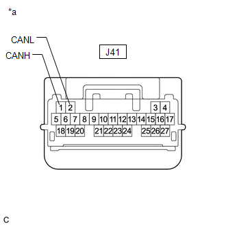
(c) Measure the resistance according to the value(s) in the table below.
Standard Resistance:
| Tester Connection | Condition | Specified Condition |
|---|---|---|
| J41-1 (CANH) - J41-2 (CANL) | Cable disconnected from negative (-) battery terminal | 54 to 69 Ω |
| NG | .gif) | REPAIR OR REPLACE CAN BRANCH LINES OR CONNECTOR (CERTIFICATION ECU (SMART KEY ECU ASSEMBLY)) |
|
.gif)
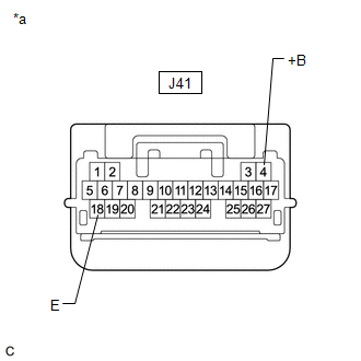
| 2. | CHECK HARNESS AND CONNECTOR (POWER SOURCE CIRCUIT) |
| (a) Measure the resistance according to the value(s) in the table below. Standard Resistance:
|
|
(b) Reconnect the cable to the negative (-) battery terminal.
(c) Measure the voltage according to the value(s) in the table below.
Standard Voltage:
| Tester Connection | Condition | Specified Condition |
|---|---|---|
| J41-4 (+B) - Body ground | Always | 11 to 14 V |
| OK | | REPLACE CERTIFICATION ECU (SMART KEY ECU ASSEMBLY) |
| NG | | REPAIR OR REPLACE HARNESS OR CONNECTOR (POWER SOURCE CIRCUIT) |
 Center Airbag Sensor Communication Stop Mode
DESCRIPTION Detection Item Symptom Trouble Area Center Airbag Sensor Communication Stop Mode Either condition is met:
"Airbag" is not displayed on the CAN Bus Check screen of the Techs ...
 Combination Meter ECU Communication Stop Mode
DESCRIPTION Detection Item Symptom Trouble Area Combination Meter ECU Communication Stop Mode Either condition is met:
"Combination Meter" is not displayed on the CAN Bus Check screen ...
Other materials:
Lexus RX (RX 350L, RX450h) 2016-2026 Repair Manual > Occupant Classification System: Front Occupant Classification Sensor LH Collision Detection (B1785)
DESCRIPTION DTC B1785 is stored when the occupant detection ECU receives a collision detection signal sent by the front occupant classification sensor LH in the case of an accident. DTC B1785 is also stored when the front seat assembly RH is subjected to a strong impact, even if an actual accident d ...
Lexus RX (RX 350L, RX450h) 2016-2026 Repair Manual > Back Door Lock: Inspection
INSPECTION PROCEDURE 1. INSPECT BACK DOOR LOCK ASSEMBLY *a Clockwise *b Counterclockwise *c Over-latch *d Full-latch *e Half-latch *f Open-latch *g Component without harness connected (Back Door Lock Assembly) (a) Apply battery voltage to the door lock mo ...
Lexus RX (RX 350L, RX450h) 2016-{YEAR} Owners Manual
- For your information
- Pictorial index
- For safety and security
- Instrument cluster
- Operation of each component
- Driving
- Lexus Display Audio system
- Interior features
- Maintenance and care
- When trouble arises
- Vehicle specifications
- For owners
Lexus RX (RX 350L, RX450h) 2016-{YEAR} Repair Manual

0.0098