Lexus RX (RX 350L, RX450h) 2016-2026 Repair Manual: Terminals Of Ecu
TERMINALS OF ECU
HINT:
Check from the rear of the connector while it is connected to the components.
RADIO RECEIVER ASSEMBLY
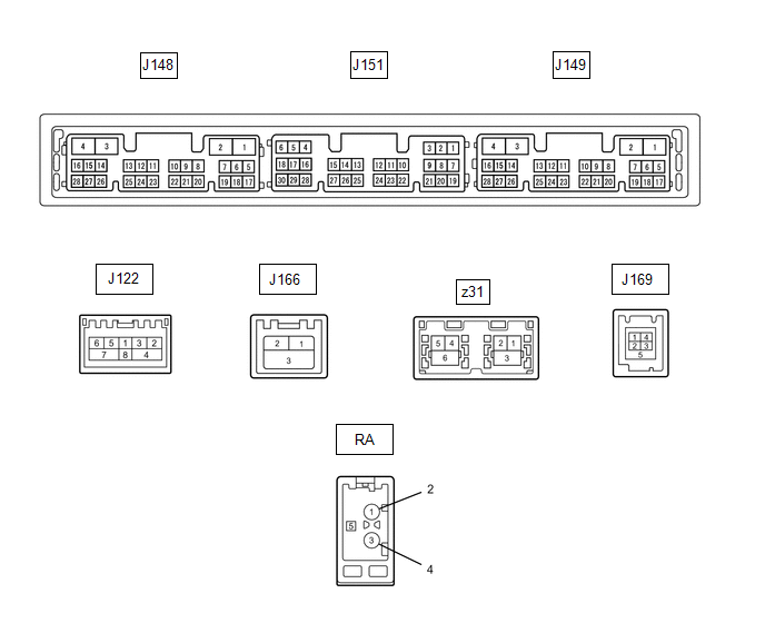
| Terminal No. (Symbol) | Wiring Color | Terminal Description | Condition | Specified Condition |
|---|---|---|---|---|
| J151-1 (VMTF) - J148-1 (GND1) | Y - W-B | Visual mute signal | Engine switch on (ACC) | 3.5 V or higher → Below 1 V → 3.5 V or higher |
| J151-5 (CNH1) | V | Local bus communication signal | - | - |
| J151-6 (CNL1) | W | Local bus communication signal | - | - |
| J151-13 (CANH) | BE | CAN communication signal | - | - |
| J151-14 (CANL) | W | CAN communication signal | - | - |
| J151-15 (ILL+) - J148-1 (GND1) | V - W-B | Illumination signal | Light control switch off | Below 1 V |
| Light control switch in tail or head position | 11 to 14 V | |||
| J151-16 (ILL-) - J148-1 (GND1) | W - W-B | Illumination signal | Light control switch off | Below 1 V |
| Light control switch in tail or head position | Pulse generation | |||
| J151-19 (IG) - J148-1 (GND1) | L - W-B | Power source (IG) | Engine switch off | Below 1 V |
| Engine switch on (IG) | 11 to 14 V | |||
| J151-21 (MIN+) - J148-1 (GND1) | P - W-B | Microphone voice signal | See "Microphone Check" in Operation Check | - |
| J151-22 (MIN-) - Body ground | G - Body ground | Microphone voice signal | See "Microphone Check" in Operation Check | - |
| J151-23 (MACC) - J148-1 (GND1) | L - W-B | Microphone power supply | Engine switch off | Below 1 V |
| Engine switch on (ACC) | 4 to 6 V | |||
| J151-24 (SGND) - Body ground | Shielded - Body ground | Shield ground | Always | Below 1 Ω |
| J151-25 (SNS2) - J148-1 (GND1) | SB - W-B | Microphone connection detection signal | Always | Below 1 V |
| J148-1 (GND1) - Body ground | W-B - Body ground | Ground | Always | Below 1 Ω |
| J148-2 (GND2) - Body ground | R - Body ground | Ground | Always | Below 1 Ω |
| J148-3 (+B) - J148-1 (GND1) | B - W-B | Power source (+B) | Always | 11 to 14 V |
| J148-4 (+B1) - J148-1 (GND1) | LA-BE - W-B | Power source (+B) | Always | 11 to 14 V |
| J148-5 (TX1+) | GR | AVC-LAN communication signal | - | - |
| J148-6 (TX1-) | V | AVC-LAN communication signal | - | - |
| J148-10 (AGND) - Body ground | Shielded - Body ground | Shield ground | Always | Below 1 Ω |
| J148-11 (VAL+) - J148-13 (VA-) | G - P | Sound signal (Left) | External device system playing (when No. 1 stereo jack adapter assembly used) | A waveform synchronized with sound signals is output |
| J148-12 (VAR+) - J148-13 (VA-) | L - P | Sound signal (Right) | External device system playing (when No. 1 stereo jack adapter assembly used) | A waveform synchronized with sound signals is output |
| J148-13 (VA-) - J148-1 (GND1) | R - W-B | Sound signal ground | Always | Below 1 V |
| J148-14 (ADPG) - J148-1 (GND1) | BE - W-B | External device connection detection signal | External device connected | Below 1 V |
| External device not connected | 1.1 to 1.9 V | |||
| J148-15 (ACC1) - J148-1 (GND1) | SB - W-B | Power source (ACC) | Engine switch off | Below 1 V |
| Engine switch on (ACC) | 11 to 14 V | |||
| J148-16 (ACC) - J148-1 (GND1) | L - W-B | Power source (ACC) | Engine switch off | Below 1 V |
| Engine switch on (ACC) | 11 to 14 V | |||
| J148-21 (SW1) - J148-24 (SWG) | V - L | Steering pad switch signal | No switch pushed | 2.97 to 3.56 V |
| Seek+ switch pushed | 0.27 to 0.35 V | |||
| Seek- switch pushed | 0.86 to 1.03 V | |||
| Volume+ switch pushed | 1.51 to 1.79 V | |||
| Volume- switch pushed | 2.22 to 2.66 V | |||
| J148-22 (SW2) - J148-24 (SWG) | G - L | Steering pad switch signal | No switch pushed | 2.97 to 3.56 V |
| MODE switch pushed | 0.27 to 0.35 V | |||
| On/off hook switch pushed | 1.51 to 1.79 V | |||
| Voice switch pushed | 2.22 to 2.66 V | |||
| J148-24 (SWG) - Body ground | L - Body ground | Steering pad switch signal | Always | Below 1 Ω |
| J148-27 (SPD) - J148-1 (GND1) | BR - W-B | Vehicle speed signal | See "Vehicle Signal Check Mode" in Operation Check | - |
| J149-7 (SUP) - J148-1 (GND1) | R - W-B | Start up signal | 20 seconds elapse after turning the engine switch on (ACC) | 11 to 14 V |
| J149-19 (RST)* | W | - | - | - |
| J149-22 (SI+) - J148-1 (GND1) | Y - W-B | Voice signal | Voice guidance sounding | A waveform synchronized with sound is output |
| J149-23 (SI-) - J148-1 (GND1) | BR - W-B | Voice signal | Voice guidance sounding | A waveform synchronized with sound is output |
| J149-24 (SGND) - J148-1 (GND1) | Shielded - W-B | Shield ground | Always | Below 1 Ω |
| J149-25 (MCO+) - J149-26 (MCO-) | R - G | Microphone voice signal | See "Check Microphone (DCU)" in Operation Check | - |
| J149-26 (MCO-) - J148-1 (GND1) | G - W-B | Microphone voice signal | See "Check Microphone (DCU)" in Operation Check | - |
| J149-28 (REV2) - J148-1 (GND1) | GR - W-B | Reverse signal | Engine running, shift position not in R → in R | 2 V or less → 11 to 14 V |
| J166-1 (GVI-) | - | Video signal (Digital) | - | - |
| J166-2 (GVI+) | - | Video signal (Digital) | - | - |
| J166-3 (GVG1) - Body ground | Shielded - Body ground | Shield ground | Always | Below 1 Ω |
| z31-1 (GV2-) | - | Video signal (Digital) | - | - |
| z31-2 (GV2+) | - | Video signal (Digital) | - | - |
| z31-3 (GVG2) - Body ground | Shielded - Body ground | Shield ground | Always | Below 1 Ω |
| z31-4 (US4+) | - | USB communication line | - | - |
| z31-5 (US4-) | - | USB communication line | - | - |
| z31-6 (UGD4) - Body ground | Shielded - Body ground | Shield ground | Always | Below 1 Ω |
| J122-1 (WUO) | W | MOST communication wake-up signal | - | - |
| J122-2 (MI+) | - | MOST communication signal | - | - |
| J122-3 (MI-) | - | MOST communication signal | - | - |
| J122-4 (SLDI) | Shielded | Shield ground | - | - |
| J122-5 (MO+) | - | MOST communication signal | - | - |
| J122-6 (MO-) | - | MOST communication signal | - | - |
| J122-7 (SLDO) | Shielded | Shield ground | - | - |
| J169-1 (USV1) | - | Power source | - | - |
| J169-2 (US1-) | - | Data signal | - | - |
| J169-3 (US1+) | - | Data signal | - | - |
| J169-4 (UGD1) | - | Ground | - | - |
| J169-5 (USG1) - Body ground | Shielded - Body ground | Shield ground | Always | Below 1 Ω |
| RA-5 (ANT+) - J148-1 (GND1) | - - W-B | Power source of antenna | Engine switch on (ACC) Radio switch on and AM or FM selected | 11 to 14 V |
- *: It is connected, but not used
NAVIGATION ECU
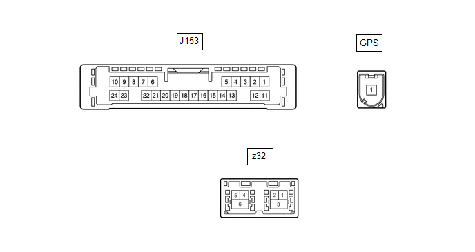
| Terminal No. (Symbol) | Wiring Color | Terminal Description | Condition | Specified Condition |
|---|---|---|---|---|
| J153-6 (VOI+) - J153-23 (GND) | Y - W-B | Voice signal | Voice guidance sounding | A waveform synchronized with sound is output |
| J153-7 (VOI-) - J153-23 (GND) | BR - W-B | Voice signal | Voice guidance sounding | A waveform synchronized with sound is output |
| J153-8 (SLD1) - Body ground | Shielded - Body ground | Shield ground | Always | Below 1 Ω |
| J153-9 (SPD) - J153-23 (GND) | W - W-B | Vehicle speed signal | See "Check GPS and Vehicle Sensors" in Operation Check | - |
| J153-10 (+B) - J153-23 (GND) | SB - W-B | Power source (+B) | Always | 11 to 14 V |
| J153-13 (MIC+) - J153-23 (GND) | R - W-B | Microphone voice signal | See "Microphone Check (MEU)" in Operation Check | - |
| J153-14 (MIC-) - Body ground | G - Body ground | Microphone voice signal | See "Microphone Check (MEU)" in Operation Check | - |
| J153-19 (REV2) - J153-23(GND) | GR - W-B | Reverse signal | Engine running, shift position not in R → in R | 2 V or less → 11 to 14 V |
| J153-21 (SUP) - J153-23 (GND) | R - W-B | Power source (ACC) | 20 seconds elapse after turning the engine switch on (ACC) | 11 to 14 V |
| J153-22 (RST)* | W | - | - | - |
| J153-23 (GND) - Body ground | W-B - Body ground | Ground | Always | Below 1 Ω |
| z32-1 (GVO-) | - | Video signal (Digital) | - | - |
| z32-2 (GVO+) | - | Video signal (Digital) | - | - |
| z32-3 (GVG1) - Body ground | Shielded - Body ground | Shield ground | Always | Below 1 Ω |
| z32-4 (US4+) | - | USB communication line | - | - |
| z32-5 (US4-) | - | USB communication line | - | - |
| z32-6 (UGD4) - Body ground | Shielded - Body ground | Shield ground | Always | Below 1 Ω |
- *: It is connected, but not used
STEREO COMPONENT AMPLIFIER ASSEMBLY
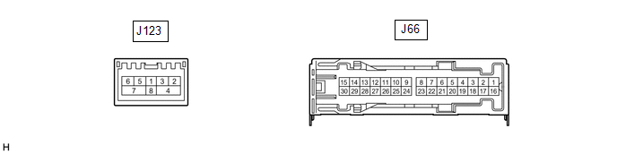
| Terminal No. (Symbol) | Wiring Color | Terminal Description | Condition | Specified Condition |
|---|---|---|---|---|
| J66-1 (+B) - J66-3 (GND) | P - W-B | Power source (+B) | Always | 11 to 14 V |
| J66-3 (GND) - Body ground | W-B - Body ground | Ground | Always | Below 1 V |
| J66-4 (WFL+) - J66-3 (GND) | L - W-B | Sound signal (Front Left) | Audio system playing | A waveform synchronized with sound signals is output |
| J66-5 (WFR+) - J66-3 (GND) | G - W-B | Sound signal (Front Right) | Audio system playing | A waveform synchronized with sound signals is output |
| J66-6 (WF1+) - J66-3 (GND)*1 | GR - W-B | Sound signal (Woofer) | Audio system playing | A waveform synchronized with sound signals is output |
| J66-7 (CTR+) - J66-3 (GND) | L - W-B | Sound signal (Front Center) | Audio system playing | A waveform synchronized with sound signals is output |
| J66-10 (SL+) - J66-3 (GND)*2 | P - W-B | Sound signal (Rear Left) | Audio system playing | A waveform synchronized with sound signals is output |
| J66-11 (SR+) - J66-3 (GND)*2 | W - W-B | Sound signal (Rear Right) | Audio system playing | A waveform synchronized with sound signals is output |
| J66-12 (FL+) - J66-3 (GND) | R - W-B | Sound signal (Front Left) | Audio system playing | A waveform synchronized with sound signals is output |
| J66-13 (FR+) - J66-3 (GND) | LG - W-B | Sound signal (Front Right) | Audio system playing | A waveform synchronized with sound signals is output |
| J66-8 (RL+) - J66-3 (GND) | B - W-B | Sound signal (Rear Left) | Audio system playing | A waveform synchronized with sound signals is output |
| J66-9 (RR+) - J66-3 (GND) | R - W-B | Sound signal (Rear Right) | Audio system playing | A waveform synchronized with sound signals is output |
| J66-16 (+B2) - J66-3 (GND) | L - W-B | Power source (+B) | Always | 11 to 14 V |
| J66-17 (SPD) - J66-3 (GND) | Y - W-B | Vehicle speed signal | Engine switch on (IG) Wheel being rotated | Pulse generation |
| J66-18 (GND2) - Body ground | W-B - Body ground | Ground | Always | Below 1 V |
| J66-19 (WFL-) - J66-3 (GND) | LG - W-B | Sound signal (Front Left) | Audio system playing | A waveform synchronized with sound signals is output |
| J66-20 (WFR-) - J66-3 (GND) | R - W-B | Sound signal (Front Right) | Audio system playing | A waveform synchronized with sound signals is output |
| J66-21 (WF1-) - J66-3 (GND)*1 | W - W-B | Sound signal (Woofer) | Audio system playing | A waveform synchronized with sound signals is output |
| J66-22 (CTR-) - J66-3 (GND) | P - W-B | Sound signal (Front Center) | Audio system playing | A waveform synchronized with sound signals is output |
| J66-25 (SL-) - J66-3 (GND)*2 | R - W-B | Sound signal (Rear Left) | Audio system playing | A waveform synchronized with sound signals is output |
| J66-26 (SR-) - J66-3 (GND)*2 | GR - W-B | Sound signal (Rear Right) | Audio system playing | A waveform synchronized with sound signals is output |
| J66-27 (FL-) - J66-3 (GND) | BR - W-B | Sound signal (Front Left) | Audio system playing | A waveform synchronized with sound signals is output |
| J66-28 (FR-) - J66-3 (GND) | L - W-B | Sound signal (Front Right) | Audio system playing | A waveform synchronized with sound signals is output |
| J66-23 (RL-) - J66-3 (GND) | Y - W-B | Sound signal (Rear Left) | Audio system playing | A waveform synchronized with sound signals is output |
| J66-24 (RR-) - J66-3 (GND) | W - W-B | Sound signal (Rear Right) | Audio system playing | A waveform synchronized with sound signals is output |
| J123-2 (MI+) | B | MOST communication signal | - | - |
| J123-3 (MI-) | B | MOST communication signal | - | - |
| J123-4 (SLDI) | Shield | Shield ground | - | - |
| J123-5 (MO+) | B | MOST communication signal | - | - |
| J123-6 (MO-) | B | MOST communication signal | - | - |
| J123-7 (SLDO) | Shield | Shield ground | - | - |
| J123-8 (WUI) | W | MOST communication wake-up signal | - | - |
- *1: except 9 Speakers
- *2: for 15 Speakers
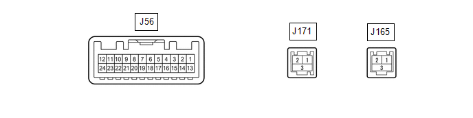
| Terminal No. (Symbol) | Wiring Color | Terminal Description | Condition | Specified Condition |
|---|---|---|---|---|
| J56-2 (ILL) - J56-13 (GND1) | LG - LA | Illumination signal | Light control switch off | Below 1 V |
| Light control switch in tail or head position | 11 to 14 V | |||
| J56-7 (TX+) | GR | AVC-LAN communication signal | - | - |
| J56-8 (V+) - J56-9 (V-)*1 | W - R | Video signal | Engine switch on (IG) Shift lever in R Camera lens not covered, displaying image | Pulse generation (Refer to waveform 1) |
| Engine switch on (IG) Shift lever in R Camera lens covered, blacking out screen | Pulse generation (Refer to waveform 2) | |||
| J56-9 (V-) - J56-13 (GND1)*1 | R - LA | Ground | Always | Below 1 V |
| J56-10 (CA+) - J56-21(CGND)*1 | B - G | Rear television camera assembly power supply | Engine switch on (ACC) | 5.5 to 7.05 V |
| J56-11 (VMT1) - J56-13 (GND1) | Y - LA | Visual mute signal | When image on display switches | 3.5 V or higher → Below 1 V → 3.5 V or higher |
| J56-12 (B) - J56-13 (GND1) | LA-B - LA | Power source (+B) | Always | 11 to 14 V |
| J56-13 (GND1) - Body ground | LA - Body ground | Ground | Always | Below 1 Ω |
| J56-19 (TX-) | V | AVC-LAN communication signal | - | - |
| J56-20 (CSLD) - Body ground*1 | Shielded - Body ground | Shield ground | Always | Below 1 Ω |
| J56-21 (CGND) - Body ground*1 | G - Body ground | Camera ground | Always | Below 1 Ω |
| J56-24 (ACC) - J56-13 (GND1) | BE - LA | Power source (ACC) | Engine switch off | Below 1 V |
| Engine switch on (ACC) | 11 to 14 V | |||
| J171-1 (GVI+)*2 | - | Video signal (Digital) | - | - |
| J171-2 (GVI-)*2 | - | Video signal (Digital) | - | - |
| J171-3 (GVG1)*2 | Shielded | Shield ground | - | - |
| J165-1 (GV+) | - | Video signal (Digital) | - | - |
| J165-2 (GV-) | - | Video signal (Digital) | - | - |
| J165-3 (GVG) | Shielded | Shield ground | - | - |
MULTI-DISPLAY ASSEMBLY
-
*1: w/ Parking Assist Monitor System
*2: w/ Panoramic View Monitor System
(a) Reference (Oscilloscope waveform):
(w/ Parking Assist Monitor System)
(1) Waveform 1 (camera lens not covered, displaying an image)
| Item | Content |
|---|---|
| Measurement terminal | J56-8 (V+) - J56-9 (V-) |
| Measurement setting | 200 mV/DIV., 50 μs/DIV. |
| Condition | Engine switch on (IG), shift lever in R |
HINT:
- The video waveform changes according to the image sent by the rear television camera assembly.
- The video waveform is constantly output when the engine switch is on (ACC).
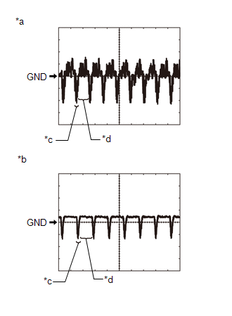
| *a | Waveform 1 (camera lens is not covered, displaying an image) |
| *b | Waveform 2 (camera lens is covered, blacking out the screen) |
| *c | Synchronization Signal |
| *d | Video Waveform |
(2) Waveform 2 (camera lens covered, blacking out the screen)
| Item | Content |
|---|---|
| Measurement terminal | J56-8 (V+) - J56-9 (V-) |
| Measurement setting | 200 mV/DIV., 50 μs/DIV. |
| Condition | Engine switch on (IG), shift lever in R |
HINT:
- The video waveform changes according to the image sent by the rear television camera assembly.
- The video waveform is constantly output when the engine switch is on (ACC).
REMOTE TOUCH (REMOTE OPERATION CONTROLLER ASSEMBLY)

| Terminal No. (Symbol) | Wiring Color | Terminal Description | Condition | Specified Condition |
|---|---|---|---|---|
| J154-1 (+B) - J154-10 (GND) | LA-SB - W-B | Power source (+B) | Always | 11 to 14 V |
| J154-2 (ILL+) - J154-10 (GND) | V - W-B | Illumination signal | Light control switch off | Below 1 V |
| Light control switch in tail or head position | 11 to 14 V | |||
| J154-5 (ILL-) - J154-10 (GND) | B - W-B | Illumination signal | Light control switch off | Below 1 V |
| Light control switch in tail or head position | Pulse generation | |||
| J154-6 (ACC) - J154-10 (GND) | R - W-B | Power source (ACC) | Engine switch on (ACC) | 11 to 14 V |
| Engine switch off | Below 1 V | |||
| J154-8 (MO-) | W | Local bus communication signal | - | - |
| J154-9 (MO+) | P | Local bus communication signal | - | - |
| J154-10 (GND) - Body ground | W-B - Body ground | Ground | Always | Below 1 Ω |
CLOCK ASSEMBLY

| Terminal No. (Symbol) | Wiring Color | Terminal Description | Condition | Specified Condition |
|---|---|---|---|---|
| J79-1 (B) - J79-7 (E) | P - W-B | Power source (+B) | Always | 11 to 14 V |
| J79-2 (ACC) - J79-7 (E) | LG - W-B | Power source (ACC) | Engine switch off | Below 1 V |
| Engine switch on (ACC) | 11 to 14 V | |||
| J79-5 (TX+1) | Y | Local bus communication signal | - | - |
| J79-6 (TX-1) | W | Local bus communication signal | - | - |
| J79-7 (E) - Body ground | W-B - Body ground | Ground | Always | Below 1 V |
COMBINATION METER ASSEMBLY
Click here .gif)
HEADUP DISPLAY (METER MIRROR SUB-ASSEMBLY) (w/ Headup Display System)
Click here
REAR TELEVISION CAMERA ASSEMBLY (w/ Parking Assist Monitor System)
Click here
PARKING ASSIST ECU (w/ Panoramic View Monitor System)
Click here
 Freeze Frame Data
FREEZE FRAME DATA CHECK FREEZE FRAME DATA (a) Connect the Techstream to the DLC3. (b) Turn the engine switch on (IG). (c) Turn the Techstream on. (d) Enter the following menus: Body Electrical / Navig ...
 Dtc Check / Clear
DTC CHECK / CLEAR CHECK DTC (CHECK USING TECHSTREAM) (a) Connect the Techstream to the DLC3. (b) Turn the engine switch on (IG) and wait for 90 seconds. (c) Turn the Techstream on. (d) Enter the follo ...
Other materials:
Lexus RX (RX 350L, RX450h) 2016-2026 Repair Manual > Fuel Pump (for Tmmc Made): Removal
REMOVAL CAUTION / NOTICE / HINT The necessary procedures (adjustment, calibration, initialization or registration) that must be performed after parts are removed and installed, or replaced during fuel pump removal/installation are shown below. Necessary Procedures After Parts Removed/Installed/Repla ...
Lexus RX (RX 350L, RX450h) 2016-2026 Repair Manual > Dynamic Radar Cruise Control System: Parts Location
PARTS LOCATION ILLUSTRATION *1 MILLIMETER WAVE RADAR SENSOR ASSEMBLY *2 FORWARD RECOGNITION CAMERA *3 SKID CONTROL ECU (BRAKE ACTUATOR ASSEMBLY) *4 ECM ILLUSTRATION *A for TFT Meter Type *B for Optitron Meter Type *1 STOP LIGHT SWITCH ASSEMBLY *2 SPIRAL CAB ...
Lexus RX (RX 350L, RX450h) 2016-{YEAR} Owners Manual
- For your information
- Pictorial index
- For safety and security
- Instrument cluster
- Operation of each component
- Driving
- Lexus Display Audio system
- Interior features
- Maintenance and care
- When trouble arises
- Vehicle specifications
- For owners
Lexus RX (RX 350L, RX450h) 2016-{YEAR} Repair Manual

0.0102