Lexus RX (RX 350L, RX450h) 2016-2026 Repair Manual: Open in Bus 4 Main Bus Line
DESCRIPTION
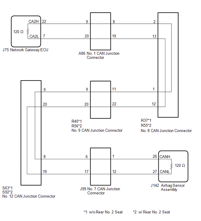
There may be an open circuit in one of the bus 4 main lines when the resistance between terminals 22 (CA2H) and 7 (CA2L) of the network gateway ECU is 70 Ω or higher.
| Symptom | Trouble Area |
|---|---|
| Resistance between terminals 22 (CA2H) and 7 (CA2L) of network gateway ECU is 70 Ω or higher. |
|
This malfunction is not related to the lines of a bus 4 branch or to ECUs or sensors connected to a bus 4 branch.
WIRING DIAGRAM
CAUTION / NOTICE / HINT
CAUTION:
When performing the confirmation driving pattern, obey all speed limits and traffic laws.
NOTICE:
- Before measuring the resistance of the CAN bus, turn the engine switch off and leave the vehicle for 1 minute or more without operating the key or any switches, or opening or closing the doors. After that, disconnect the cable from the negative (-) battery terminal and leave the vehicle for 1 minute or more before measuring the resistance.
-
After turning the engine switch off, waiting time may be required before disconnecting the cable from the negative (-) battery terminal. Therefore, make sure to read the disconnecting the cable from the negative (-) battery terminal notices before proceeding with work.
Click here
.gif)
-
Because the order of diagnosis is important to allow correct diagnosis, make sure to begin troubleshooting using How to Proceed with Troubleshooting when CAN communication system related DTCs are output.
Click here
-
After performing repairs, perform the DTC check procedure and confirm that the DTCs are not output again.
DTC check procedure: Turn the engine switch on (IG) and wait for 1 minute or more. Then operate the suspected malfunctioning system and drive the vehicle at 60 km/h (37 mph) or more for 5 minutes or more.
-
After the repair, perform the CAN bus check and check that all the ECUs and sensors connected to the CAN communication system are displayed.
Click here
HINT:
- Operating the engine switch, any other switches or a door triggers related ECU and sensor communication on the CAN. This communication will cause the resistance value to change.
- Even after DTCs are cleared, if a DTC is stored again after driving the vehicle for a while, the malfunction may be occurring due to vibration of the vehicle. In such a case, wiggling the ECUs or wire harness while performing the inspection below may help determine the cause of the malfunction.
PROCEDURE
| 1. | CHECK FOR OPEN IN CAN BUS LINES (NETWORK GATEWAY ECU) |
(a) Disconnect the cable from the negative (-) battery terminal.
| (b) Disconnect the J75 network gateway ECU connector. |
|
.png)
(c) Measure the resistance according to the value(s) in the table below.
Standard Resistance:
| Tester Connection | Condition | Specified Condition |
|---|---|---|
| J75-22 (CA2H) - J75-7 (CA2L) | Cable disconnected from negative (-) battery terminal | 108 to 132 Ω |
| OK | .gif) | REPLACE NETWORK GATEWAY ECU |
|
.gif)
| 2. | CHECK FOR OPEN IN CAN BUS LINES (AIRBAG SENSOR ASSEMBLY) |
(a) Reconnect the J75 network gateway ECU connector.
| (b) Disconnect the J142 airbag sensor assembly connector. |
|
.png)
(c) Measure the resistance according to the value(s) in the table below.
Standard Resistance:
| Tester Connection | Condition | Specified Condition |
|---|---|---|
| J142-26 (CANH) - J142-27 (CANL) | Cable disconnected from negative (-) battery terminal | 108 to 132 Ω |
| Result | Proceed to |
|---|---|
| OK | A |
| NG (w/o Rear No. 2 Seat) | B |
| NG (w/ Rear No. 2 Seat) | C |
| A | | REPLACE AIRBAG SENSOR ASSEMBLY |
| C | | GO TO STEP 8 |
|
| 3. | CHECK FOR OPEN IN CAN BUS LINES (NO. 9 CAN JUNCTION CONNECTOR) |
(a) Reconnect the J142 airbag sensor assembly connector.
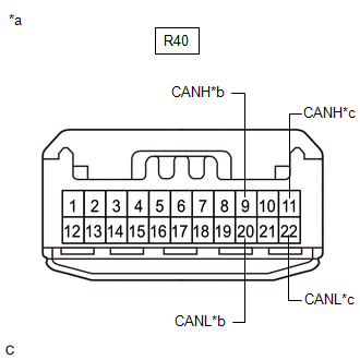
| (b) Disconnect the R40 No. 9 CAN junction connector. |
|
(c) Measure the resistance according to the value(s) in the table below.
Standard Resistance:
| Tester Connection | Condition | Specified Condition | Connected to |
|---|---|---|---|
| R40-9 (CANH) - R40-20 (CANL) | Cable disconnected from negative (-) battery terminal | 108 to 132 Ω | No. 12 CAN junction connector |
| R40-11 (CANH) - R40-22 (CANL) | Cable disconnected from negative (-) battery terminal | 108 to 132 Ω | No. 8 CAN junction connector |
| Result | Proceed to |
|---|---|
| OK | A |
| NG (No. 8 CAN junction connector main lines) | B |
| NG (No. 12 CAN junction connector main lines) | C |
| A | | REPLACE NO. 9 CAN JUNCTION CONNECTOR |
| C | | GO TO STEP 6 |
|
| 4. | CHECK FOR OPEN IN CAN BUS LINES (NO. 1 CAN JUNCTION CONNECTOR) |
(a) Reconnect the R40 No. 9 CAN junction connector.
| (b) Disconnect the A86 No. 1 CAN junction connector. |
|

(c) Measure the resistance according to the value(s) in the table below.
Standard Resistance:
| Tester Connection | Condition | Specified Condition | Connected to |
|---|---|---|---|
| A86-8 (CANH) - A86-19 (CANL) | Cable disconnected from negative (-) battery terminal | 108 to 132 Ω | No. 8 CAN junction connector |
| A86-9 (CANH) - A86-20 (CANL) | Cable disconnected from negative (-) battery terminal | 108 to 132 Ω | Network gateway ECU |
| Result | Proceed to |
|---|---|
| OK | A |
| NG (Network gateway ECU main lines) | B |
| NG (No. 8 CAN junction connector main lines) | C |
| A | | REPLACE NO. 1 CAN JUNCTION CONNECTOR |
| B | | REPAIR OR REPLACE CAN MAIN BUS LINES OR CONNECTOR (NETWORK GATEWAY ECU - NO. 1 CAN JUNCTION CONNECTOR) |
|
| 5. | CHECK FOR OPEN IN CAN BUS LINES (NO. 8 CAN JUNCTION CONNECTOR) |
(a) Reconnect the A86 No. 1 CAN junction connector.
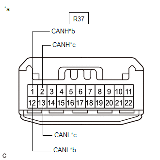
| (b) Disconnect the R37 No. 8 CAN junction connector. |
|
(c) Measure the resistance according to the value(s) in the table below.
Standard Resistance:
| Tester Connection | Condition | Specified Condition | Connected to |
|---|---|---|---|
| R37-1 (CANH) - R37-12 (CANL) | Cable disconnected from negative (-) battery terminal | 108 to 132 Ω | No. 9 CAN junction connector |
| R37-2 (CANH) - R37-13 (CANL) | Cable disconnected from negative (-) battery terminal | 108 to 132 Ω | No. 1 CAN junction connector |
| Result | Proceed to |
|---|---|
| OK | A |
| NG (No. 1 CAN junction connector main lines) | B |
| NG (No. 9 CAN junction connector main lines) | C |
| A | | REPLACE NO. 8 CAN JUNCTION CONNECTOR |
| B | | REPAIR OR REPLACE CAN MAIN BUS LINES OR CONNECTOR (NO. 1 CAN JUNCTION CONNECTOR - NO. 8 CAN JUNCTION CONNECTOR) |
| C | | REPAIR OR REPLACE CAN MAIN BUS LINES OR CONNECTOR (NO. 8 CAN JUNCTION CONNECTOR - NO. 9 CAN JUNCTION CONNECTOR) |
| 6. | CHECK FOR OPEN IN CAN BUS LINES (NO. 12 CAN JUNCTION CONNECTOR) |
(a) Reconnect the R40 No. 9 CAN junction connector.
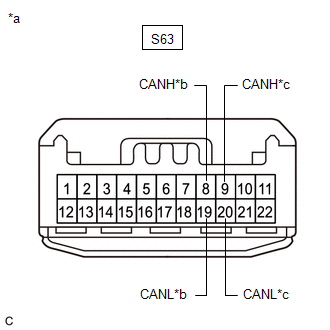
| (b) Disconnect the S63 No. 12 CAN junction connector. |
|
(c) Measure the resistance according to the value(s) in the table below.
Standard Resistance:
| Tester Connection | Condition | Specified Condition | Connected to |
|---|---|---|---|
| S63-8 (CANH) - S63-19 (CANL) | Cable disconnected from negative (-) battery terminal | 108 to 132 Ω | No. 7 CAN junction connector |
| S63-9 (CANH) - S63-20 (CANL) | Cable disconnected from negative (-) battery terminal | 108 to 132 Ω | No. 9 CAN junction connector |
| Result | Proceed to |
|---|---|
| OK | A |
| NG (No. 7 CAN junction connector main lines) | B |
| NG (No. 9 CAN junction connector main lines) | C |
| A | | REPLACE NO. 12 CAN JUNCTION CONNECTOR |
| C | | REPAIR OR REPLACE CAN MAIN BUS LINES OR CONNECTOR (NO. 9 CAN JUNCTION CONNECTOR - NO. 12 CAN JUNCTION CONNECTOR) |
|
| 7. | CHECK FOR OPEN IN CAN BUS LINES (NO. 7 CAN JUNCTION CONNECTOR) |
(a) Reconnect the S63 No. 12 CAN junction connector.
| (b) Disconnect the J99 No. 7 CAN junction connector. |
|
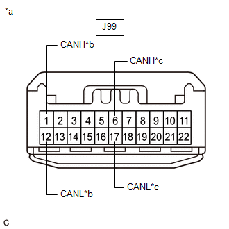
(c) Measure the resistance according to the value(s) in the table below.
Standard Resistance:
| Tester Connection | Condition | Specified Condition | Connected to |
|---|---|---|---|
| J99-1 (CANH) - J99-12 (CANL) | Cable disconnected from negative (-) battery terminal | 108 to 132 Ω | Airbag sensor assembly |
| J99-6 (CANH) - J99-17 (CANL) | Cable disconnected from negative (-) battery terminal | 108 to 132 Ω | No. 12 CAN junction connector |
| Result | Proceed to |
|---|---|
| OK | A |
| NG (Airbag sensor assembly main lines) | B |
| NG (No. 12 CAN junction connector main lines) | C |
| A | | REPLACE NO. 7 CAN JUNCTION CONNECTOR |
| B | | REPAIR OR REPLACE CAN MAIN BUS LINES OR CONNECTOR (AIRBAG SENSOR ASSEMBLY - NO. 7 CAN JUNCTION CONNECTOR) |
| C | | REPAIR OR REPLACE CAN MAIN BUS LINES OR CONNECTOR (NO. 7 CAN JUNCTION CONNECTOR - NO. 12 CAN JUNCTION CONNECTOR) |
| 8. | CHECK FOR OPEN IN CAN BUS LINES (NO. 9 CAN JUNCTION CONNECTOR) |
(a) Reconnect the J142 airbag sensor assembly connector.
| (b) Disconnect the R56 No. 9 CAN junction connector. |
|

(c) Measure the resistance according to the value(s) in the table below.
Standard Resistance:
| Tester Connection | Condition | Specified Condition | Connected to |
|---|---|---|---|
| R56-9 (CANH) - R56-20 (CANL) | Cable disconnected from negative (-) battery terminal | 108 to 132 Ω | No. 12 CAN junction connector |
| R56-11 (CANH) - R56-22 (CANL) | Cable disconnected from negative (-) battery terminal | 108 to 132 Ω | No. 8 CAN junction connector |
| Result | Proceed to |
|---|---|
| OK | A |
| NG (No. 8 CAN junction connector main lines) | B |
| NG (No. 12 CAN junction connector main lines) | C |
| A | | REPLACE NO. 9 CAN JUNCTION CONNECTOR |
| C | | GO TO STEP 11 |
|
| 9. | CHECK FOR OPEN IN CAN BUS LINES (NO. 1 CAN JUNCTION CONNECTOR) |
(a) Reconnect the R56 No. 9 CAN junction connector.
| (b) Disconnect the A86 No. 1 CAN junction connector. |
|
(c) Measure the resistance according to the value(s) in the table below.
Standard Resistance:
| Tester Connection | Condition | Specified Condition | Connected to |
|---|---|---|---|
| A86-8 (CANH) - A86-19 (CANL) | Cable disconnected from negative (-) battery terminal | 108 to 132 Ω | No. 8 CAN junction connector |
| A86-9 (CANH) - A86-20 (CANL) | Cable disconnected from negative (-) battery terminal | 108 to 132 Ω | Network gateway ECU |
| Result | Proceed to |
|---|---|
| OK | A |
| NG (Network gateway ECU main lines) | B |
| NG (No. 8 CAN junction connector main lines) | C |
| A | | REPLACE NO. 1 CAN JUNCTION CONNECTOR |
| B | | REPAIR OR REPLACE CAN MAIN BUS LINES OR CONNECTOR (NETWORK GATEWAY ECU - NO. 1 CAN JUNCTION CONNECTOR) |
|
| 10. | CHECK FOR OPEN IN CAN BUS LINES (NO. 8 CAN JUNCTION CONNECTOR) |
(a) Reconnect the A86 No. 1 CAN junction connector.
| (b) Disconnect the R55 No. 8 CAN junction connector. |
|
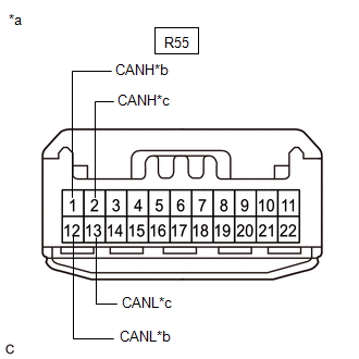
(c) Measure the resistance according to the value(s) in the table below.
Standard Resistance:
| Tester Connection | Condition | Specified Condition | Connected to |
|---|---|---|---|
| R55-1 (CANH) - R55-12 (CANL) | Cable disconnected from negative (-) battery terminal | 108 to 132 Ω | No. 9 CAN junction connector |
| R55-2 (CANH) - R55-13 (CANL) | Cable disconnected from negative (-) battery terminal | 108 to 132 Ω | No. 1 CAN junction connector |
| Result | Proceed to |
|---|---|
| OK | A |
| NG (No. 1 CAN junction connector main lines) | B |
| NG (No. 9 CAN junction connector main lines) | C |
| A | | REPLACE NO. 8 CAN JUNCTION CONNECTOR |
| B | | REPAIR OR REPLACE CAN MAIN BUS LINES OR CONNECTOR (NO. 1 CAN JUNCTION CONNECTOR - NO. 8 CAN JUNCTION CONNECTOR) |
| C | | REPAIR OR REPLACE CAN MAIN BUS LINES OR CONNECTOR (NO. 8 CAN JUNCTION CONNECTOR - NO. 9 CAN JUNCTION CONNECTOR) |
| 11. | CHECK FOR OPEN IN CAN BUS LINES (NO. 12 CAN JUNCTION CONNECTOR) |
(a) Reconnect the R56 No. 9 CAN junction connector.
| (b) Disconnect the S92 No. 12 CAN junction connector. |
|

(c) Measure the resistance according to the value(s) in the table below.
Standard Resistance:
| Tester Connection | Condition | Specified Condition | Connected to |
|---|---|---|---|
| S92-8 (CANH) - S92-19 (CANL) | Cable disconnected from negative (-) battery terminal | 108 to 132 Ω | No. 7 CAN junction connector |
| S92-9 (CANH) - S92-20 (CANL) | Cable disconnected from negative (-) battery terminal | 108 to 132 Ω | No. 9 CAN junction connector |
| Result | Proceed to |
|---|---|
| OK | A |
| NG (No. 7 CAN junction connector main lines) | B |
| NG (No. 9 CAN junction connector main lines) | C |
| A | | REPLACE NO. 12 CAN JUNCTION CONNECTOR |
| C | | REPAIR OR REPLACE CAN MAIN BUS LINES OR CONNECTOR (NO. 9 CAN JUNCTION CONNECTOR - NO. 12 CAN JUNCTION CONNECTOR) |
|
| 12. | CHECK FOR OPEN IN CAN BUS LINES (NO. 7 CAN JUNCTION CONNECTOR) |
(a) Reconnect the S92 No. 12 CAN junction connector.
| (b) Disconnect the J99 No. 7 CAN junction connector. |
|
(c) Measure the resistance according to the value(s) in the table below.
Standard Resistance:
| Tester Connection | Condition | Specified Condition | Connected to |
|---|---|---|---|
| J99-1 (CANH) - J99-12 (CANL) | Cable disconnected from negative (-) battery terminal | 108 to 132 Ω | Airbag sensor assembly |
| J99-6 (CANH) - J99-17 (CANL) | Cable disconnected from negative (-) battery terminal | 108 to 132 Ω | No. 12 CAN junction connector |
| Result | Proceed to |
|---|---|
| OK | A |
| NG (Airbag sensor assembly main lines) | B |
| NG (No. 12 CAN junction connector main lines) | C |
| A | | REPLACE NO. 7 CAN JUNCTION CONNECTOR |
| B | | REPAIR OR REPLACE CAN MAIN BUS LINES OR CONNECTOR (AIRBAG SENSOR ASSEMBLY - NO. 7 CAN JUNCTION CONNECTOR) |
| C | | REPAIR OR REPLACE CAN MAIN BUS LINES OR CONNECTOR (NO. 7 CAN JUNCTION CONNECTOR - NO. 12 CAN JUNCTION CONNECTOR) |
 Check Bus 4 Lines for Short Circuit
DESCRIPTION There may be a short circuit between the bus 4 main lines and/or bus 4 branch lines when the resistance between terminals 22 (CA2H) and 7 (CA2L) of the network gateway ECU is below 54 Ω. ...
 Open in One Side of Bus 4 Branch Line
DESCRIPTION If an ECU or sensor is not displayed on the CAN Bus Check screen of the Techstream and some ECUs and sensors repeatedly appear and disappear from the screen when the CAN main bus lines are ...
Other materials:
Lexus RX (RX 350L, RX450h) 2016-2026 Repair Manual > Rear Power Seat Control System(for Second Row): Back Door Courtesy Switch Circuit
DESCRIPTION The fold seat control ECU receives switch operation signals, the driving condition signal and back door courtesy light switch assembly signal and operates the rear power seat according to these signals. WIRING DIAGRAM PROCEDURE 1. CHECK BACK DOOR LOCK ASSEMBLY (BACK DOOR COURTESY ...
Lexus RX (RX 350L, RX450h) 2016-2026 Repair Manual > Automatic Transaxle System: Manual Shifting Test
MANUAL SHIFTING TEST MANUAL SHIFTING TEST HINT:
Using this test, it can be determined whether a problem is in an electrical circuit or if it is a mechanical problem in the transaxle.
If any abnormalities are found in the following test, the problem is in the transaxle itself.
(a) Disconnect ...
Lexus RX (RX 350L, RX450h) 2016-{YEAR} Owners Manual
- For your information
- Pictorial index
- For safety and security
- Instrument cluster
- Operation of each component
- Driving
- Lexus Display Audio system
- Interior features
- Maintenance and care
- When trouble arises
- Vehicle specifications
- For owners
Lexus RX (RX 350L, RX450h) 2016-{YEAR} Repair Manual

0.017