Lexus RX (RX 350L, RX450h) 2016-2026 Repair Manual: Terminals Of Ecu
TERMINALS OF ECU
CHECK INSTRUMENT PANEL JUNCTION BLOCK ASSEMBLY AND MAIN BODY ECU (MULTIPLEX NETWORK BODY ECU)
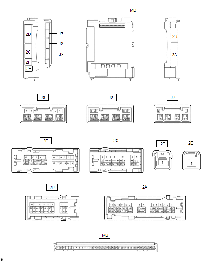
(a) Disconnect the MB main body ECU (multiplex network body ECU) connector.
Click here .gif)
(b) Measure the voltage and resistance according to the value(s) in the table below.
HINT:
Measure the values on the wire harness side with the connectors disconnected.
| Terminal No. (Symbol) | Wiring Color | Terminal Description | Condition | Specified Condition |
|---|---|---|---|---|
| MB-11 (GND1) - Body ground | - | Ground | Always | Below 1 Ω |
| MB-31 (BECU) - Body ground | - | Battery power supply | Always | 11 to 14 V |
| MB-30 (ACC) - Body ground | - | ACC power supply | Engine switch on (ACC) | 11 to 14 V |
| MB-30 (ACC) - Body ground | - | ACC power supply | Engine switch off | Below 1 V |
| MB-32 (IG) - Body ground | - | IG power supply | Engine switch on (IG) | 11 to 14 V |
| MB-32 (IG) - Body ground | - | IG power supply | Engine switch off | Below 1 V |
(c) Reconnect the MB main body ECU (multiplex network body ECU) connector.
(d) Check for pulses according to the value(s) in the table below.
| Terminal No. (Symbol) | Wiring Color | Terminal Description | Condition | Specified Condition |
|---|---|---|---|---|
| 2D-25 - Body ground | L - Body ground | LIN communication line | Engine switch on (IG) | Pulse generation |
| 2B-17 - Body ground | Y - Body ground | LIN communication line | Engine switch on (IG) | Pulse generation |
CHECK POWER WINDOW REGULATOR MOTOR ASSEMBLY LH

(a) Disconnect the N13 power window regulator motor assembly LH connector.
(b) Measure the voltage and resistance according to the value(s) in the table below.
HINT:
Measure the values on the wire harness side with the connector disconnected.
| Terminal No. (Symbol) | Wiring Color | Terminal Description | Condition | Specified Condition |
|---|---|---|---|---|
| N13-2 (B) - Body ground | L - Body ground | Battery power supply | Always | 11 to 14 V |
| N13-1 (E) - Body ground | W-B - Body ground | Ground | Always | Below 1 Ω |
(c) Reconnect the N13 power window regulator motor assembly LH connector.
(d) Check for pulses according to the value(s) in the table below.
| Terminal No. (Symbol) | Wiring Color | Terminal Description | Condition | Specified Condition |
|---|---|---|---|---|
| N13-9 (LIN) - Body ground | B - Body ground | LIN communication line | Engine switch on (IG) | Pulse generation |
CHECK POWER WINDOW REGULATOR MOTOR ASSEMBLY RH

(a) Disconnect the M13 power window regulator motor assembly RH connector.
(b) Measure the voltage and resistance according to the value(s) in the table below.
HINT:
Measure the values on the wire harness side with the connector disconnected.
| Terminal No. (Symbol) | Wiring Color | Terminal Description | Condition | Specified Condition |
|---|---|---|---|---|
| M13-2 (B) - Body ground | G - Body ground | Battery power supply | Always | 11 to 14 V |
| M13-1 (E) - Body ground | W-B - Body ground | Ground | Always | Below 1 Ω |
(c) Reconnect the M13 power window regulator motor assembly RH connector.
(d) Check for pulses according to the value(s) in the table below.
| Terminal No. (Symbol) | Wiring Color | Terminal Description | Condition | Specified Condition |
|---|---|---|---|---|
| M13-9 (LIN) - Body ground | B - Body ground | LIN communication line | Engine switch on (IG) | Pulse generation |
CHECK POWER WINDOW REGULATOR MOTOR ASSEMBLY (for Rear RH Door)

(a) Disconnect the O1 power window regulator motor assembly (for rear RH door) connector.
(b) Measure the voltage and resistance according to the value(s) in the table below.
HINT:
Measure the values on the wire harness side with the connector disconnected.
| Terminal No. (Symbol) | Wiring Color | Terminal Description | Condition | Specified Condition |
|---|---|---|---|---|
| O1-2 (B) - Body ground | P - Body ground | Battery power supply | Always | 11 to 14 V |
| O1-1 (E) - Body ground | W-B - Body ground | Ground | Always | Below 1 Ω |
(c) Reconnect the O1 power window regulator motor assembly (for rear RH door) connector.
(d) Check for pulses according to the value(s) in the table below.
| Terminal No. (Symbol) | Wiring Color | Terminal Description | Condition | Specified Condition |
|---|---|---|---|---|
| O1-9 (LIN) - Body ground | B - Body ground | LIN communication line | Engine switch on (IG) | Pulse generation |
CHECK POWER WINDOW REGULATOR MOTOR ASSEMBLY (for Rear LH Door)

(a) Disconnect the P1 power window regulator motor assembly (for rear LH door) connector.
(b) Measure the voltage and resistance according to the value(s) in the table below.
HINT:
Measure the values on the wire harness side with the connector disconnected.
| Terminal No. (Symbol) | Wiring Color | Terminal Description | Condition | Specified Condition |
|---|---|---|---|---|
| P1-2 (B) - Body ground | L - Body ground | Battery power supply | Always | 11 to 14 V |
| P1-1 (E) - Body ground | W-B - Body ground | Ground | Always | Below 1 Ω |
(c) Reconnect the P1 power window regulator motor assembly (for rear LH door) connector.
(d) Check for pulses according to the value(s) in the table below.
| Terminal No. (Symbol) | Wiring Color | Terminal Description | Condition | Specified Condition |
|---|---|---|---|---|
| P1-9 (LIN) - Body ground | B - Body ground | LIN communication line | Engine switch on (IG) | Pulse generation |
CHECK MULTIPLEX NETWORK MASTER SWITCH ASSEMBLY

(a) Disconnect the N7 multiplex network master switch assembly connector.
(b) Measure the voltage and resistance according to the value(s) in the table below.
HINT:
Measure the values on the wire harness side with the connector disconnected.
| Terminal No. (Symbol) | Wiring Color | Terminal Description | Condition | Specified Condition |
|---|---|---|---|---|
| N7-11 (B) - Body ground | B - Body ground | Battery power supply | Always | 11 to 14 V |
| N7-12 (GND) - Body ground | W-B - Body ground | Ground | Always | Below 1 Ω |
(c) Reconnect the N7 multiplex network master switch assembly connector.
(d) Check for pulses according to the value(s) in the table below.
| Terminal No. (Symbol) | Wiring Color | Terminal Description | Condition | Specified Condition |
|---|---|---|---|---|
| N7-17 (LIN1) - Body ground | B - Body ground | LIN communication line | Engine switch on (IG) | Pulse generation |
CHECK SLIDING ROOF ECU (SLIDING ROOF DRIVE GEAR SUB-ASSEMBLY) (w/ Sliding Roof System)

(a) Disconnect the U2 sliding roof ECU (sliding roof drive gear sub-assembly) connector.
(b) Measure the voltage and resistance according to the value(s) in the table below.
HINT:
Measure the values on the wire harness side with the connector disconnected.
| Terminal No. (Symbol) | Wiring Color | Terminal Description | Condition | Specified Condition |
|---|---|---|---|---|
| U2-1 (B) - Body ground | P - Body ground | Battery power supply | Always | 11 to 14 V |
| U2-2 (E) - Body ground | W-B - Body ground | Ground | Always | Below 1 Ω |
(c) Reconnect the U2 sliding roof ECU (sliding roof drive gear sub-assembly) connector.
(d) Check for pulses according to the value(s) in the table below.
| Terminal No. (Symbol) | Wiring Color | Terminal Description | Condition | Specified Condition |
|---|---|---|---|---|
| U2-7 (MPX1) - Body ground | GR - Body ground | LIN communication line | Engine switch on (IG) | Pulse generation |
CHECK SLIDING ROOF ECU (SLIDING ROOF DRIVE GEAR ASSEMBLY) (w/ Panoramic Moon Roof System)
(a) Disconnect the U2 sliding roof ECU (sliding roof drive gear assembly) connector.
(b) Measure the voltage and resistance according to the value(s) in the table below.
HINT:
Measure the values on the wire harness side with the connector disconnected.
| Terminal No. (Symbol) | Wiring Color | Terminal Description | Condition | Specified Condition |
|---|---|---|---|---|
| U2-1 (B) - Body ground | P - Body ground | Battery power supply | Always | 11 to 14 V |
| U2-2 (E) - Body ground | W-B - Body ground | Ground | Always | Below 1 Ω |
(c) Reconnect the U2 sliding roof ECU (sliding roof drive gear assembly) connector.
(d) Check for pulses according to the value(s) in the table below.
| Terminal No. (Symbol) | Wiring Color | Terminal Description | Condition | Specified Condition |
|---|---|---|---|---|
| U2-7 (MPX1) - Body ground | GR - Body ground | LIN communication line | Engine switch on (IG) | Pulse generation |
CHECK ROOF SUNSHADE ECU (SLIDING ROOF DRIVE GEAR ASSEMBLY) (w/ Panoramic Moon Roof System)

(a) Disconnect the w1 roof sunshade ECU (sliding roof drive gear assembly) connector.
(b) Measure the voltage and resistance according to the value(s) in the table below.
HINT:
Measure the values on the wire harness side with the connector disconnected.
| Terminal No. (Symbol) | Wiring Color | Terminal Description | Condition | Specified Condition |
|---|---|---|---|---|
| w1-1 (+B) - Body ground | R - Body ground | Battery power supply | Always | 11 to 14 V |
| w1-2 (E) - Body ground | B - Body ground | Ground | Always | Below 1 Ω |
(c) Reconnect the w1 roof sunshade ECU (sliding roof drive gear assembly) connector.
(d) Check for pulses according to the value(s) in the table below.
| Terminal No. (Symbol) | Wiring Color | Terminal Description | Condition | Specified Condition |
|---|---|---|---|---|
| w1-7 (LIN) - Body ground | W - Body ground | LIN communication line | Engine switch on (IG) | Pulse generation |
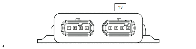
CHECK KICK DOOR CONTROL SENSOR (w/ Hands Free Power Back Door)
(a) Disconnect the Y9 kick door control sensor connector.
(b) Measure the voltage and resistance according to the value(s) in the table below.
HINT:
Measure the values on the wire harness side with the connector disconnected.
| Terminal No. (Symbol) | Wiring Color | Terminal Description | Condition | Specified Condition |
|---|---|---|---|---|
| Y9-1 (+B) - Body ground | V - Body ground | Battery power supply | Always | 11 to 14 V |
| Y9-4 (GND) - Body ground | W-B - Body ground | Ground | Always | Below 1 Ω |
(c) Reconnect the Y9 kick door control sensor connector.
(d) Check for pulses according to the value(s) in the table below.
| Terminal No. (Symbol) | Wiring Color | Terminal Description | Condition | Specified Condition |
|---|---|---|---|---|
| Y9-1 (LIN) - Body ground | B - Body ground | LIN communication line | Engine switch on (IG) | Pulse generation |
CHECK CERTIFICATION ECU (SMART KEY ECU ASSEMBLY)
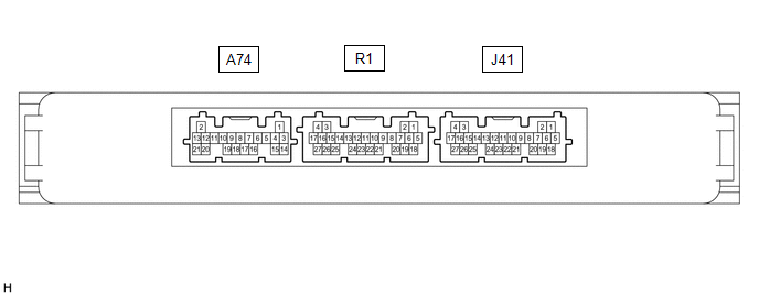
(a) Disconnect the J41 certification ECU (smart key ECU assembly) connector.
(b) Measure the voltage and resistance according to the value(s) in the table below.
HINT:
Measure the values on the wire harness side with the connector disconnected.
| Terminal No. (Symbol) | Wiring Color | Terminal Description | Condition | Specified Condition |
|---|---|---|---|---|
| J41-18 (E) - Body ground | W-B - Body ground | Ground | Always | Below 1 Ω |
| J41-4 (+B) - Body ground | V - Body ground | +B power supply | Always | 11 to 14 V |
(c) Reconnect the J41 certification ECU (smart key ECU assembly) connector.
(d) Check for pulses according to the value(s) in the table below.
| Terminal No. (Symbol) | Wiring Color | Terminal Description | Condition | Specified Condition |
|---|---|---|---|---|
| J41-13 (LIN) - Body ground | LG - Body ground | LIN communication line | Engine switch on (IG) | Pulse generation |
CHECK STEERING LOCK ECU (STEERING LOCK ACTUATOR OR UPPER BRACKET ASSEMBLY)

(a) Disconnect the L1 steering lock ECU (steering lock actuator or upper bracket assembly) connector.
(b) Measure the resistance and voltage according to the value(s) in the table below.
| Terminal No. (Symbol) | Wiring Color | Terminal Description | Condition | Specified Condition |
|---|---|---|---|---|
| L1-1 (GND) - Body ground | W-B - Body ground | Ground | Always | Below 1 Ω |
| L1-7 (B) - Body ground | V - Body ground | Battery power supply | Always | 11 to 14 V |
(c) Reconnect the L1 steering lock ECU (steering lock actuator or upper bracket assembly) connector.
(d) Check for pulses according to the value(s) in the table below.
| Terminal No. (Symbol) | Wiring Color | Terminal Description | Condition | Specified Condition |
|---|---|---|---|---|
| L1-5 (LIN) - Body ground | R - Body ground | LIN communication line | Engine switch on (IG) | Pulse generation |
CHECK ID CODE BOX (IMMOBILISER CODE ECU)

(a) Disconnect the J36 ID code box (immobiliser code ECU) connector.
(b) Measure the voltage and resistance according to the value(s) in the table below.
HINT:
Measure the values on the wire harness side with the connector disconnected.
| Terminal No. (Symbol) | Wiring Color | Terminal Description | Condition | Specified Condition |
|---|---|---|---|---|
| J36-5 (GND) - Body ground | B - Body ground | Ground | Always | Below 1 Ω |
| J36-1 (+B) - Body ground | B - Body ground | +B power supply | Always | 11 to 14 V |
(c) Reconnect the J36 ID code box (immobiliser code ECU) connector.
(d) Check for pulses according to the value(s) in the table below.
| Terminal No. (Symbol) | Wiring Color | Terminal Description | Condition | Specified Condition |
|---|---|---|---|---|
| J36-2 (LIN1) - Body ground | B - Body ground | LIN communication line | Engine switch on (IG) | Pulse generation |
 Diagnosis System
DIAGNOSIS SYSTEM DESCRIPTION The main body ECU (multiplex network body ECU) and certification ECU (smart key ECU assembly) control the LIN communication system. LIN communication system data and Diagn ...
 Data List / Active Test
DATA LIST / ACTIVE TEST DATA LIST HINT: Using the Techstream to read the Data List allows the values or states of switches, sensors, actuators and other items to be read without removing any parts. Th ...
Other materials:
Lexus RX (RX 350L, RX450h) 2016-2026 Repair Manual > Lighting System (w/o Automatic Headlight Beam Level Control System): Parts Location
PARTS LOCATION ILLUSTRATION *A w/ Automatic High Beam System - - *1 HEADLIGHT ASSEMBLY LH - HEADLIGHT UNIT LH *2 HEADLIGHT ASSEMBLY RH - HEADLIGHT UNIT RH *3 SIDE TURN SIGNAL LIGHT ASSEMBLY LH *4 SIDE TURN SIGNAL LIGHT ASSEMBLY RH *5 FRONT DOOR OUTSIDE HANDLE ASSE ...
Lexus RX (RX 350L, RX450h) 2016-2026 Repair Manual > Lighting System (w/ Automatic Headlight Beam Level Control System): Front Fog Light Circuit
DESCRIPTION The main body ECU (multiplex network body ECU) controls the front fog lights. WIRING DIAGRAM CAUTION / NOTICE / HINT NOTICE:
Inspect the fuses for circuits related to this system before performing the following procedure.
Before replacing the main body ECU (multiplex network body E ...
Lexus RX (RX 350L, RX450h) 2016-{YEAR} Owners Manual
- For your information
- Pictorial index
- For safety and security
- Instrument cluster
- Operation of each component
- Driving
- Lexus Display Audio system
- Interior features
- Maintenance and care
- When trouble arises
- Vehicle specifications
- For owners
Lexus RX (RX 350L, RX450h) 2016-{YEAR} Repair Manual

0.0108